• Welcome to the new SAOCA website. Already a member? Simply click Log In/Sign Up up and to the right and use your same username and password from the old site. If you've forgotten your password, please send an email to membership@sunbeamalpine.org for assistance.

    If you're new here, click Log In/Sign Up and enter your information. We'll approve your account as quickly as possible, typically in about 24 hours. If it takes longer, you were probably caught in our spam/scam filter.

    Enjoy.

The Journey Begins - Series I V6 Restomod

Bill Eisinger

Platinum Level Sponsor
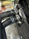
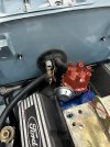
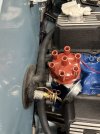
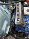
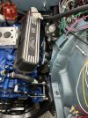
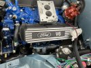
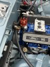
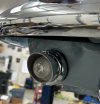
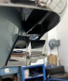
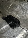
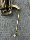
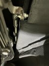
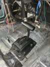
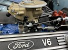
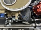
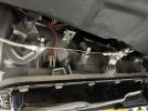
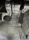
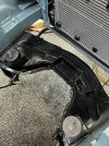
Well, under the category of “2 steps forward and 1 step back” we encountered a few issues that needed to be rectified. It’s a long story but, when doing the structural work for the car, my body/paint guy pretty much ignored the notebook full of pictures and procedures (supplied by DanR) and did his own thing in setting up the engine location and position…short story was that the nose of the engine was raised almost 2 inches higher than DanR’s design which created a whole myriad of problems that are subject to another discussion. We didn’t really discover the impact of this until we had the engine in…So, out came the engine and we re-fabbed the engine mounts and got them into proper location. Upon dropping the engine back in, it was then discovered that the crank pulley would not clear the cross member…it’s a bit of a mystery as to why…I’m thinking that I’m perhaps using a bit larger crank pulley than others have used plus it’s a double pulley (for the air conditioner) so that exacerbates the issue. Out came the plasma torch and welder and we went to town on the cross brace putting a notch in it….it’s not the most beautiful welding in the world but, thankfully, it’s pretty much all hidden when the engine is installed. Next week we’ll put the engine back in and see if we can keep moving the ball forward!
 

Attachments

  • IMG_2035.jpeg
    IMG_2035.jpeg
    2.2 MB · Views: 47
Last edited:

Beamin

Platinum Level Sponsor
I feel your pain. I think I had my engine in and out 3 times before I had all the kinks worked out, and I still haven’t returned the engine hoist I borrowed for fear that before I get the car fully road worthy, I’m going to have to pull it out again.
 

Aladin Sane

Diamond Level Sponsor
The 302 and c4 were in the car when I bought it, but none of it was wired and the carb was not on top of the intake. I hope it all fits under the bonet. I pulled the engine and trans out in two parts. I will try to put it back the same way.
 

Bill Eisinger

Platinum Level Sponsor
I‘m going with an A4LD automatic trans on this build…also putting it and the engine in separately….its a big trans and a little bit of a pain but I have some buddies to lend an extra hand and my shop has a lift which makes it a lot easier on the body…my friends and I are all experienced Mustang guys (no Sunbeam experience) so the group of us trying to straighten out all the issues on this Sunbeam is a bit like the Keystone Cops…
 
Last edited:

Bill Eisinger

Platinum Level Sponsor
Among the many challenges that I’ve encountered (many of which were unintentionally self-induced) has been getting sufficient clearance between the heater/AC lines coming through the firewall and the distributor. If I had thought it through I would have routed the lines through a bulkhead fitting elsewhere on the firewall but by the time I figured out there was a problem it was too late to turn back. So, after a lot of trial and error I ended up using a Bosch distributor instead of the Duraspark that has been commonly spec’d…the Bosch has a somewhat smaller cap diameter plus the vacuum advance canister is positioned in a vertical alignment as opposed to horizontal as is the case for most distributors…this creates quite a bit of additional space between the distributor and firewall. Additionally, I used hoses with 90 degree elbows and positioned everything such that the elbow is flush with the firewall to create maximum clearance.

All in all, it’s perhaps not the best way to go but it’s going to work fine and looks good as well.
 

Attachments

  • IMG_2057.jpeg
    IMG_2057.jpeg
    1 MB · Views: 41
  • IMG_2064.jpeg
    IMG_2064.jpeg
    1.3 MB · Views: 41
  • IMG_2065.jpeg
    IMG_2065.jpeg
    1.2 MB · Views: 41

Bill Eisinger

Platinum Level Sponsor
All right, after countless phone calls with DanR, pulling the engine in and out at least 4 times, modifying the engine mount brackets and then modifying a second set of brackets the engine is now in place…or at least as close as it’s going to get. The final location is going to be too close to the radiator for a radiator fan on the engine side…fingers crossed that the two electric pushers will blow enough wind to keep things cool. Once the engine was finally in I learned how much fun it is to install the headers…my hat is off to you guys that do all this stuff without a lift…
 

Attachments

  • IMG_0105.jpeg
    IMG_0105.jpeg
    1.6 MB · Views: 37
  • IMG_0104.jpeg
    IMG_0104.jpeg
    1.7 MB · Views: 37
  • IMG_0107.jpeg
    IMG_0107.jpeg
    1.7 MB · Views: 38
  • IMG_0106.jpeg
    IMG_0106.jpeg
    1.5 MB · Views: 38

260Alpine

Silver Level Sponsor
Todd must have the Capri intake. The Mustang II and Ranger use the Autolite ( Holley pattern ) 2 barrel instead of the Weber the Capri used.
 

Bill Eisinger

Platinum Level Sponsor
Just a tiny bit of progress to show but I think this is one of the coolest items on an early Sunbeam from a visual standpoint…I sourced a set of Spartos from a forum member and had them rechromed. Added new two wire bulb sockets for improved ground conductivity and installed new LED bulbs…the form factor of these lamps just shouts early 60’s and the space age!
 

Attachments

  • IMG_0112.jpeg
    IMG_0112.jpeg
    1.2 MB · Views: 42
  • IMG_0113.jpeg
    IMG_0113.jpeg
    988.2 KB · Views: 42

Bill Eisinger

Platinum Level Sponsor
Moving on to the transmission now that the engine is sorted. This week’s fun has been trying to figure out how to connect the floor shifter to the A4LD trans…went through a number of iterations and settled on a universal shifter rod from an out fit called Shift Works. One stumbling block was that my body/paint guy didn’t leave enough clearance for any hardware connected to the A4LD shift arm…did a little surgery on the tunnel and added a “Dan Gurney bubble” so that the shift arm could move. It looks pretty ugly now but carpet and the console will make it go away. It looks like this is going to work…it shifts through all the positions nicely.

Safety Note: Did you know that you can set sound deadening material on fire with welding sparks?…that was an exciting few minutes!
 

Attachments

  • IMG_0126.jpeg
    IMG_0126.jpeg
    1.8 MB · Views: 31
  • IMG_0130.jpeg
    IMG_0130.jpeg
    2.2 MB · Views: 30
  • IMG_0133.jpeg
    IMG_0133.jpeg
    1,020.9 KB · Views: 30
  • IMG_0135.jpeg
    IMG_0135.jpeg
    1.6 MB · Views: 31

Bill Blue

Platinum Level Sponsor
Are the shifting positions correct? DanR and I used home made versions of your system (looks grand) but the shifting action was backward. Test by putting the tranny in "Park" and try to move the car.
Bill
 

Bill Eisinger

Platinum Level Sponsor
More small incremental progress which has taken far longer than it should. It looks like I might be breaking new ground with my particular combination of components…EFI with stock intake, custom valve covers from JR-Cast and the A4LD auto transmission…these pieces together all contributed to some dimensional challenges in allowing the the carb throttle lever to move freely as well as attaching the transmission kick down cable.

My engine builder fabricated an inch and a half thick spacer to raise the EFI throttle body to roughly the same height as if it were on an Offy intake. Even with that, the throttle lever had to be trimmed a bit to allow it to rotate without contacting the valve covers.

The next problem was finding a bracket that the would 1) fit on the Sniper EFI and 2) provide the correct alignment for the throttle and kick down cables…I went through a couple iterations of Lokar brackets as well as a Holley bracket and despite being advertised as fitting the Holley Sniper, they all had one or more problems. I finally came across a bracket from an outfit called IH Parts America that, with a little modification, turned out to work pretty well…the bracket is a little big and clunky but it works and for the most part, will be covered by the air cleaner.

To get it all to work I had to connect the kick down cable on the inside of the throttle lever instead of the outside but it works just fine although a bit more cumbersome to adjust. I’m using a Lokar throttle pedal and cable as well as a Lokar kick down cable…Lokar prices are somewhat breath taking but it’s all well built and is working out perfect for my situation.

On to moving forward as DanR often reminds me…
 

Attachments

  • IMG_0167.jpeg
    IMG_0167.jpeg
    1.6 MB · Views: 35
  • IMG_0168.jpeg
    IMG_0168.jpeg
    1.3 MB · Views: 36
  • IMG_0169.jpeg
    IMG_0169.jpeg
    982.2 KB · Views: 36
  • IMG_0170.jpeg
    IMG_0170.jpeg
    1.7 MB · Views: 35

husky drvr

Platinum Level Sponsor
EFI with stock intake
Bill,

After viewing these pics, this is just a curiosity question rather than about your build. I've not researched much about TB EFI, the reason for the curiosity.

Is the TBI body restricted for use as a downdraft installation? Since it is a pressurized injection system, I wouldn't think there are any parts of the system which are gravity referenced. Might require linkage mods for a different orientation, but that's nothing new.

Mainly just curious if your TBI might be orientated for side draft flow?

Just an "out of the box" question,
 
Top