-
Welcome to the new SAOCA website. Already a member? Simply click Log In/Sign Up up and to the right and use your same username and password from the old site. If you've forgotten your password, please send an email to membership@sunbeamalpine.org for assistance.
If you're new here, click Log In/Sign Up and enter your information. We'll approve your account as quickly as possible, typically in about 24 hours. If it takes longer, you were probably caught in our spam/scam filter.
Enjoy.
You are using an out of date browser. It may not display this or other websites correctly.
You should upgrade or use an alternative browser.
You should upgrade or use an alternative browser.
Duratec Installation
- Thread starter Bill Blue
- Start date
Hi Bill,
Why not weld a bracket with a small roller (plastic if possible) onto the plenum, just high enough to let the cable clear the plenum? The cable would just roll the roller and wouldn't cause major problems.
Jose")
I think that is what I am going to have to do. My initial thought was a wedge between the throttle body and log, but it does not move the throttle shaft very much. I have a hunk of nylon, think it would suffice?
Bill
RootesRacer
Donation Time
Bill,
If I understand your problem correctly, why dont you mount a pulley type linkage to the throttle lever. You pull on the cable and the pulley converts that into rotary motion. If you make the pulley variable ratio (eccentric), you can make the throttle progressive, meaning that the first part of the throttle (where you cruise) requires more linear pull per degree than the later portion.
My webers linkage uses this pulley scheme and it works very well.
This looks to be to be a pretty simple solution to your problem.
EDIT: On closer inspection of your picture, I see it already has a pulley type setup, but it you add your own pulley, you could go over the top of the plenum instead of under the bottom as you planned.
Bill,
EDIT: On closer inspection of your picture, I see it already has a pulley type setup, but it you add your own pulley, you could go over the top of the plenum instead of under the bottom as you planned.
Are you speaking of two pulleys, resulting in an "S" configuration for the cable?
Bill
RootesRacer
Donation Time
No, one pulley only directly mounted to the TB lever, allows the cable to enter at any tangential angle relative to the pulley.
Okay, I think I see what you are suggesting. Keep in mind there is less than an inch of clearance between the hood and log. I don't think that would leave enough room for the cable to make the required 45 degree bend. But maybe it would, I don't know. Probably time to scope out the accelerator cable market. I've been using bicycle control cables. Any suggestions?
Bill
Bill
RootesRacer
Donation Time
I got one from redline weber (part# 99006.103) this may be actually a magnetti marelli/weber part number, it looks like one.
It is a legitimate automotive accelerator cable, about 50% thicker than bicycle brake cable, finer twist to the cable too. It came with some of fittings not unlike the cable adjusters on bike brake cables, one for the firewall and one for the bracket at the TB. It is open cable on the cockpit side, with a motorcycle type barrel on the TB side.
No clue what it costs, I got mine on barter.
Looks like a motorcycle brake cable would be similar if the weber part is pricey.
Hi Bill,
I think simply putting the throttle body at an angle, wouldn't get you where you want to go. because the plenum would still be at the same height. All it would do is point the cable at a different angle and you'd still need the roller to get past it. With a roller, you could get one of the throttle cable kits from an auto parts store and you'd be home free, because they are inexpensive (about $20.00) work great and look very professional.
The only other thing I can see that would work, would be to offset the throttle body, using the piece of nylon you were reffereing to, as an adapter. Offset it just enough to raise the centerline of the throttle body, to where the cable would clear. Doesn't look like it would take much. If you offset it, you'd need to bore the I.D. at the angle it would take to match the two so you don't introduce a restriction in the air stream.
Jose
I ordered and received a universal cable kit from Amazon. $15.26 with shipping. That is a kit that I saw elsewhere for thirty bucks. I'm finding Amazon to be a good source of stuff. Anyway, while waiting of the kit, I decided to leave things as they are for a while. After the engine is reinstalled, I'll look into the possibility of relocation. I don't want to go to the trouble of making something only to find it interferes with something. Done that too many times already. Here is photo of the the throttle body and a string to duplicate the route that must be taken by the cable.
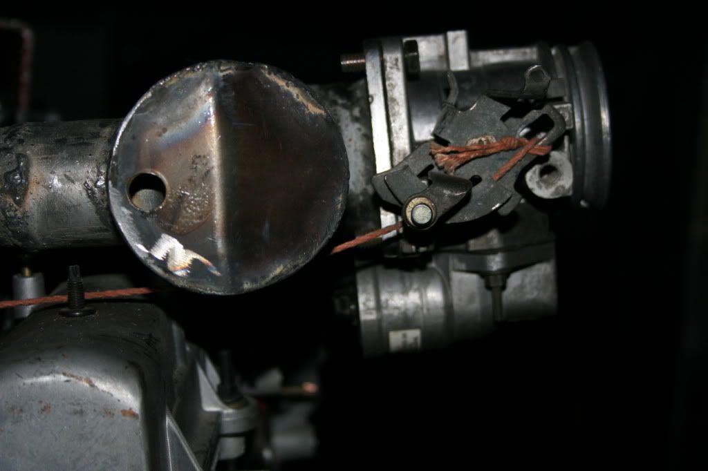
I'm thinking that if I can lower the TB and set it at an angle, the roller might only be needed at WOT, which is the position the photo shows it.
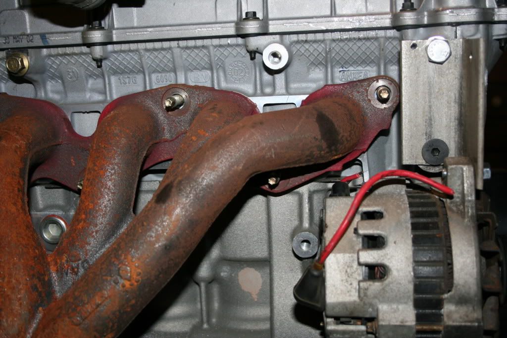
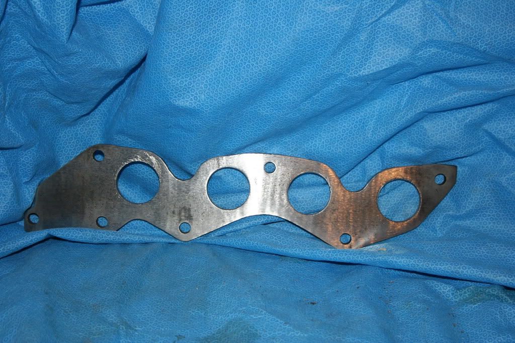
So, onward to the exhaust. Cut out the flange, using the technique used to make the intake flange. All went well, in spite of an incredibly dull bandsaw blade (new one on the way), I'd say I have less than two hours in it. Definitely better than paying $70 (plus shipping) for a "store bought". Here is photo of it on the engine.
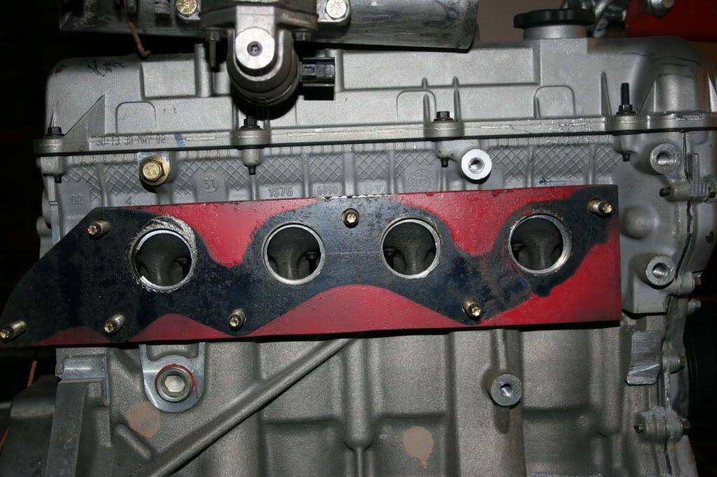
The red area is the area of the flange that extends beyond the cast iron exhaust. Question of the day, would it be okay to trim to the outline of the cast iron, or should the steel be left with more "meat" on it. They are about the same thickness.
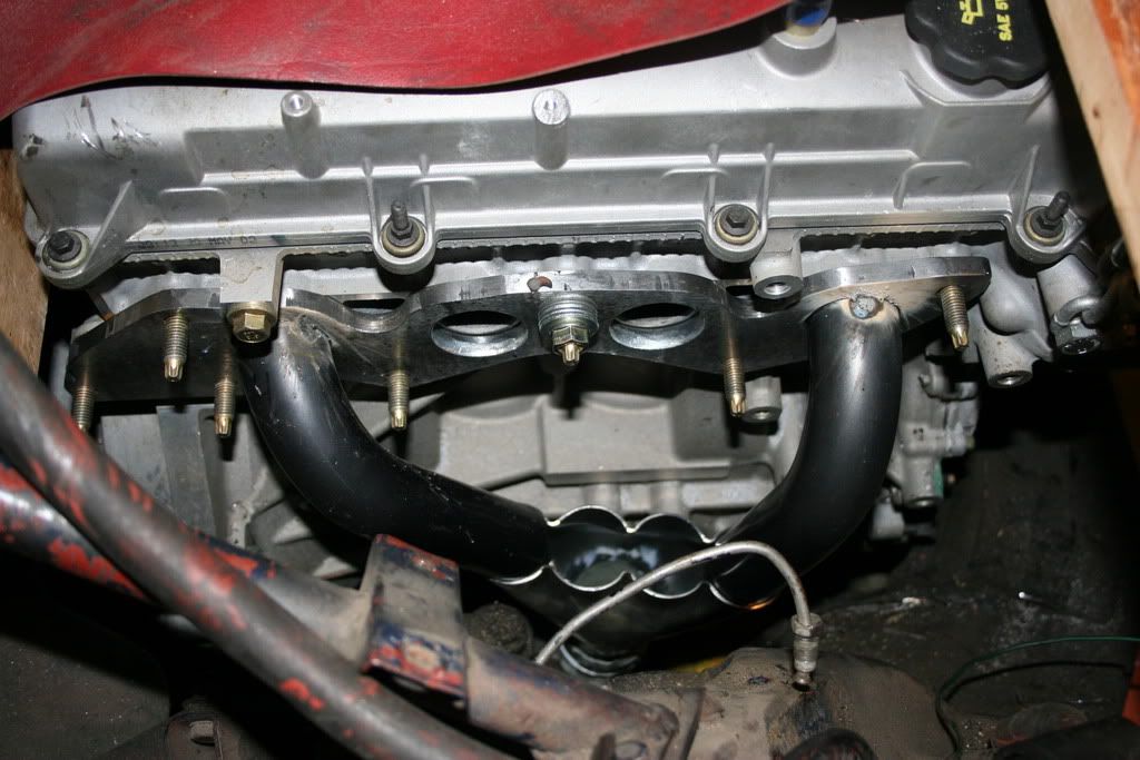
Also been working on locating the alternator. An immediate problem of clearance pops up. Here is my dilemma:
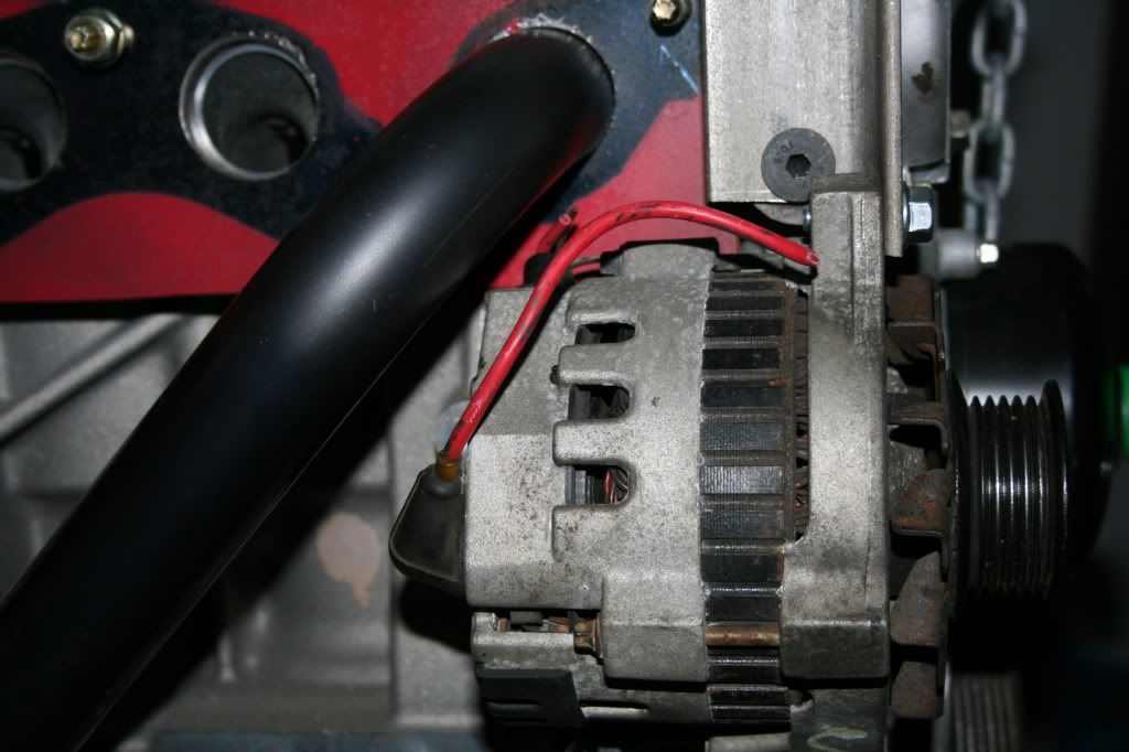
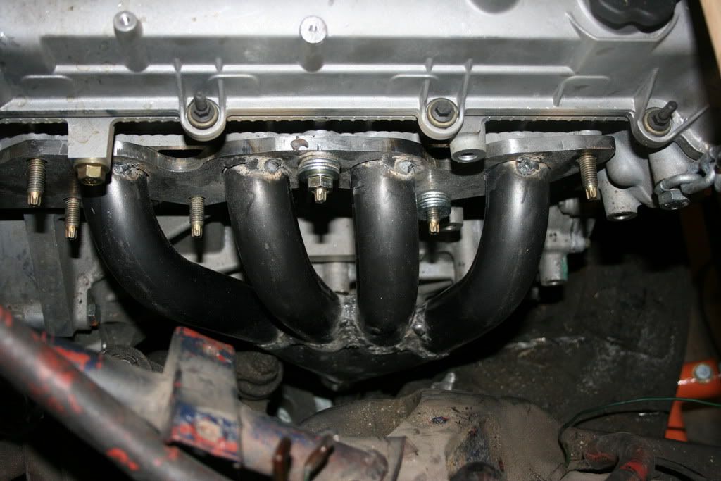
As you can see, things are pretty close, especially if you consider the route the exhaust has to take out of the engine compartment. Here is a photo the Pinto exhaust.
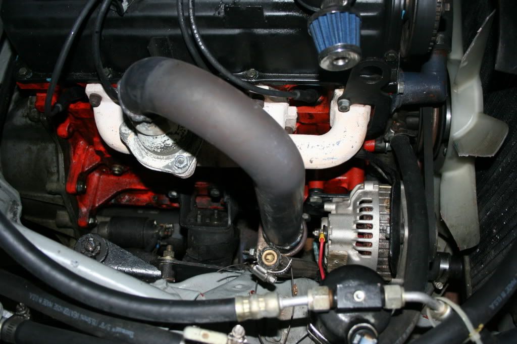
Note the route that has to be taken is immediately behind the alternator. I don't see how that can be done, especially if I use any type of header. This is a complex situation. The exhaust has to bend under the engine, so a long, multitube header is out. It would require the engine to be installed after the header was in place. Don't think so. This is a low buck project, so I'm not going to drag it to a muffler shop 75 miles away and pay big bucks for a one off header. I think I will drop the engine back in place, build a shorty 4 into 1 header with flat collector, then find a suitable place for the alternator. That is going to be interesting as the other side will have the AC compressor.
Bill
I'm thinking that if I can lower the TB and set it at an angle, the roller might only be needed at WOT, which is the position the photo shows it.
So, onward to the exhaust. Cut out the flange, using the technique used to make the intake flange. All went well, in spite of an incredibly dull bandsaw blade (new one on the way), I'd say I have less than two hours in it. Definitely better than paying $70 (plus shipping) for a "store bought". Here is photo of it on the engine.
The red area is the area of the flange that extends beyond the cast iron exhaust. Question of the day, would it be okay to trim to the outline of the cast iron, or should the steel be left with more "meat" on it. They are about the same thickness.
Also been working on locating the alternator. An immediate problem of clearance pops up. Here is my dilemma:
As you can see, things are pretty close, especially if you consider the route the exhaust has to take out of the engine compartment. Here is a photo the Pinto exhaust.
Note the route that has to be taken is immediately behind the alternator. I don't see how that can be done, especially if I use any type of header. This is a complex situation. The exhaust has to bend under the engine, so a long, multitube header is out. It would require the engine to be installed after the header was in place. Don't think so. This is a low buck project, so I'm not going to drag it to a muffler shop 75 miles away and pay big bucks for a one off header. I think I will drop the engine back in place, build a shorty 4 into 1 header with flat collector, then find a suitable place for the alternator. That is going to be interesting as the other side will have the AC compressor.
Bill
Just a photo showing how Ford addressed the exhaust/alternator clearance question:
That will not work on the Alpine as there is no room to the rear of the engine (steering arms). Besides, the exhaust has to be on the other side of the car.
Just going to have to see exactly how things work out. Boy, do I envy people that can look at stuff like this and work things out in their mind. The price I pay for lack of talent!
Bill
todd reid
Gold Level Sponsor
Bill,
Just a thought for you to keep in in your back pocket. I have seen a couple of hotrods with reverse mount alternators (this puts your wiring on the forward side - pointing toward the radiator). I can't tell from your pictures if this would help you or not. Probably falls into the category of a last resort, but it has been done before.
Just a thought for you to keep in in your back pocket. I have seen a couple of hotrods with reverse mount alternators (this puts your wiring on the forward side - pointing toward the radiator). I can't tell from your pictures if this would help you or not. Probably falls into the category of a last resort, but it has been done before.
Went for quite a while with no progress on the 'Pine. Holidays, the brake light kits and just generally feeling crappy lead to a lot of no progress.
I finally got the steering box "spacer" cut down and a phoney spacer made to hold the "spacer" in place. It is just a piece of 3/4" pine that I ran into while looking among my goodies for for a likely candidate. The pine is not good for long term, but it took only about a minute to cut it to length and drill two holes.
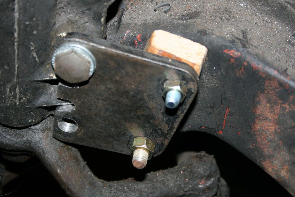
You can get an idea of how this is supposed to work. The old spacer is now used to "clamp" (more of less) the steering box in location. The long bolts holding everything in place are all wrong, but it will do for now. In addition, there will be another bolt through the original spacer into the steering box, which is now tapped. The upper hole tapped 7/16"-20, the lower 1/2"-13. Nothing special about these sizes, they are the best match for the steering box mounting holes.
I then turned my attention to dropping the engine/trans into place. Found myself thinking more about finding someone to buy the stuff than the job, so quit as soon as it was in. I don't have to do this, ever. Especially on days I don't feel like messing with it.
Bolted the makeshift "motor mounts" onto the engine and right away decided they had outlived their usefulness. They are difficult to maneuver and are in the way of fitting "real" engine mounts.
They did serve a purpose. Using them, I was able to determine my intake manifold height restrictions. As that part is now over, I decided to suspend the engine from a 2X4, resting on the fenders. Could not find a 2X4. My choices were a 2X2 or 2X6. So I chose the 2X6. It is wide, gets in the way, but such is life.
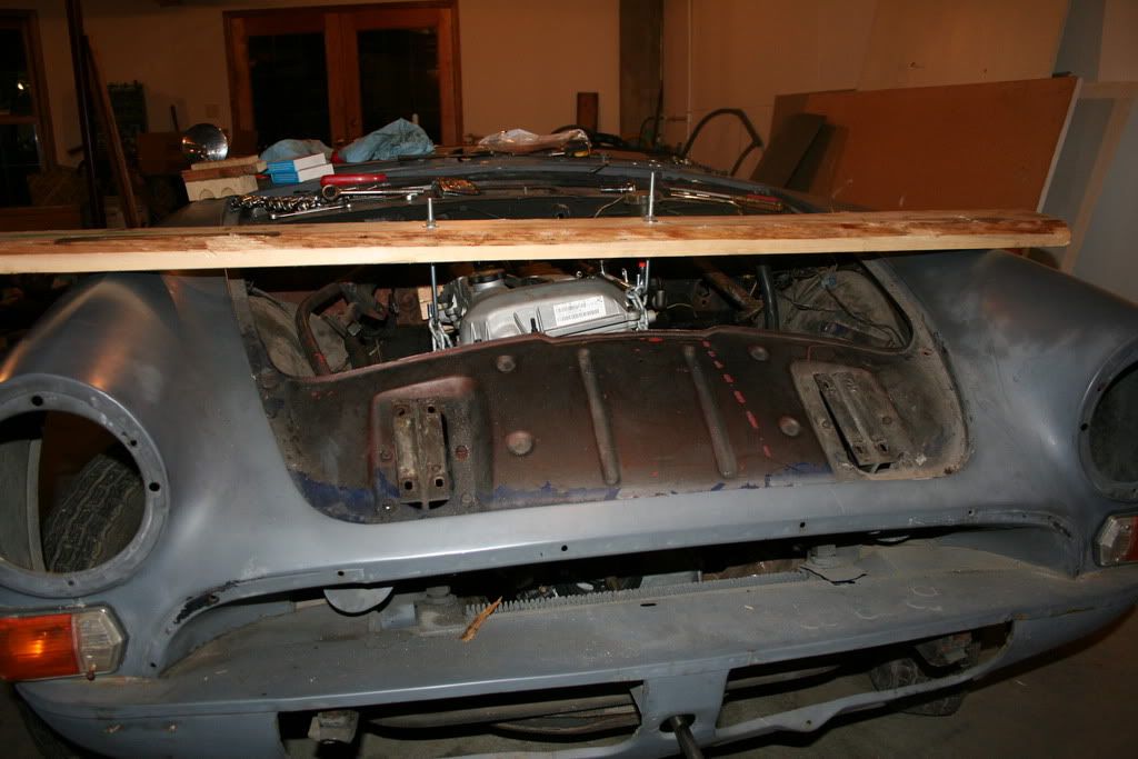
It actually works quite well. The J bolts control the engine height and angle, and I can slide the board side to side and fore and aft for final location.
Put the header flange to the dull bandsaw blade. Made the long sweeping cuts, then my new blade arrived. It is a 1/4" blade. so can cut pretty tight radius'. Here is the final job.
The two very tight radius' on the top of the flange were cut on the drill press, using a hole saw. All in all, I am pretty happy with how it turned out.
Bill
I finally got the steering box "spacer" cut down and a phoney spacer made to hold the "spacer" in place. It is just a piece of 3/4" pine that I ran into while looking among my goodies for for a likely candidate. The pine is not good for long term, but it took only about a minute to cut it to length and drill two holes.
You can get an idea of how this is supposed to work. The old spacer is now used to "clamp" (more of less) the steering box in location. The long bolts holding everything in place are all wrong, but it will do for now. In addition, there will be another bolt through the original spacer into the steering box, which is now tapped. The upper hole tapped 7/16"-20, the lower 1/2"-13. Nothing special about these sizes, they are the best match for the steering box mounting holes.
I then turned my attention to dropping the engine/trans into place. Found myself thinking more about finding someone to buy the stuff than the job, so quit as soon as it was in. I don't have to do this, ever. Especially on days I don't feel like messing with it.
Bolted the makeshift "motor mounts" onto the engine and right away decided they had outlived their usefulness. They are difficult to maneuver and are in the way of fitting "real" engine mounts.
They did serve a purpose. Using them, I was able to determine my intake manifold height restrictions. As that part is now over, I decided to suspend the engine from a 2X4, resting on the fenders. Could not find a 2X4. My choices were a 2X2 or 2X6. So I chose the 2X6. It is wide, gets in the way, but such is life.
It actually works quite well. The J bolts control the engine height and angle, and I can slide the board side to side and fore and aft for final location.
Put the header flange to the dull bandsaw blade. Made the long sweeping cuts, then my new blade arrived. It is a 1/4" blade. so can cut pretty tight radius'. Here is the final job.
The two very tight radius' on the top of the flange were cut on the drill press, using a hole saw. All in all, I am pretty happy with how it turned out.
Bill
I spent way to much time fussing with the engine location and angle, trying to find the perfect spot that allows room for the air condition pump, alternator, intake manifold and motor mounts while leaving room for the steering arms to clear the exhaust and and steering arms. Decided that spot in all likely hood does not exist. At least not in a perfect form. So I decided to "do" the exhaust and work my way through the other stuff as it comes up.
First up was the header collector. It terminates in a 2 1/4" opening and has no adapter. I happened to have a 2 1/2" adapter, so I decided a shotgun wedding was in order. Here is what I started with.
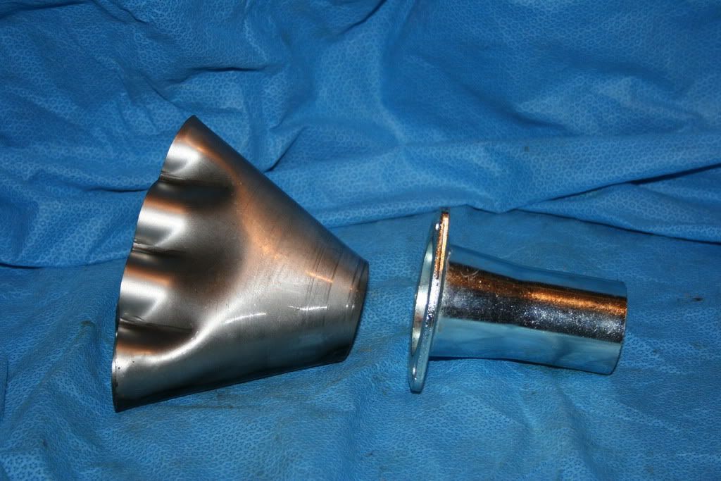
Here they are after the marriage:
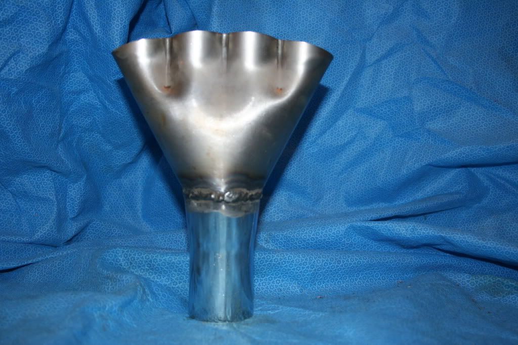
Check out that weld. I don't know why it turned out so good, thought it might be me. Not even a whole lot of splatter. I was so proud of myself. Thought I had turned that corner and was ready for the header.
So onward to the big daddy: The HEADER. Here it is with two of the primary pipes tacked in place:
It is hard to see, but the #4 pipe is not not down into the socket properly. The problem is the angle of the cut is not correct. I cut it square, it should have been on a pretty good angle. It is best to think of such tragedies as "God just gave me a chance to improve my welding skills". Unfortunately, I'm a non believer, so it has to go down as a screwup.
Bill
First up was the header collector. It terminates in a 2 1/4" opening and has no adapter. I happened to have a 2 1/2" adapter, so I decided a shotgun wedding was in order. Here is what I started with.
Here they are after the marriage:
Check out that weld. I don't know why it turned out so good, thought it might be me. Not even a whole lot of splatter. I was so proud of myself. Thought I had turned that corner and was ready for the header.
So onward to the big daddy: The HEADER. Here it is with two of the primary pipes tacked in place:
It is hard to see, but the #4 pipe is not not down into the socket properly. The problem is the angle of the cut is not correct. I cut it square, it should have been on a pretty good angle. It is best to think of such tragedies as "God just gave me a chance to improve my welding skills". Unfortunately, I'm a non believer, so it has to go down as a screwup.
Bill
Here is the header after the screwup has been fixed and all welding done.
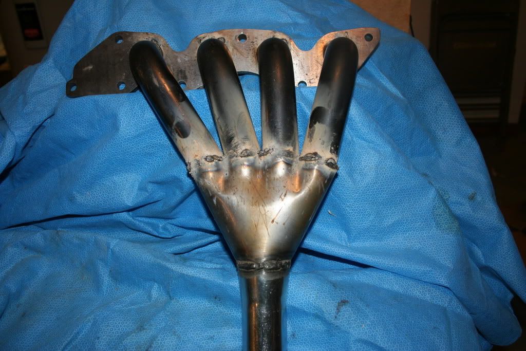
Ugly? You ain't seen nothing yet. Take a look at the backside.
U-G-L-Y
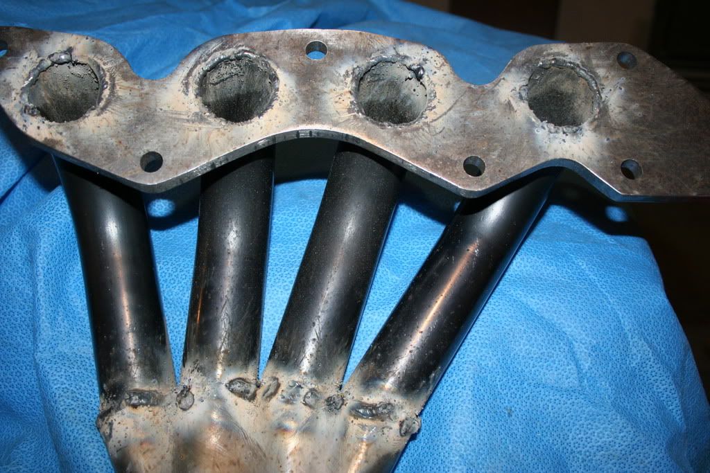
I welded the primaries to the flange on the inside, thinking that it would be best to protect the relatively thin edge of the tube from the hot gases. Spent all day today cleaning up the mess, then checked for leaks. You'd think I was making a lawn sprinkler.
Bill
Ugly? You ain't seen nothing yet. Take a look at the backside.
U-G-L-Y
I welded the primaries to the flange on the inside, thinking that it would be best to protect the relatively thin edge of the tube from the hot gases. Spent all day today cleaning up the mess, then checked for leaks. You'd think I was making a lawn sprinkler.
Bill
After much grinding, welding and water testing, I got the header to point there were just two minor weeps. I put some more weld on them and declared the job done. I think it would have been okay with the weepers and they may not be tight, but it is good enough. Just has to be. Here is the pic of the final job.
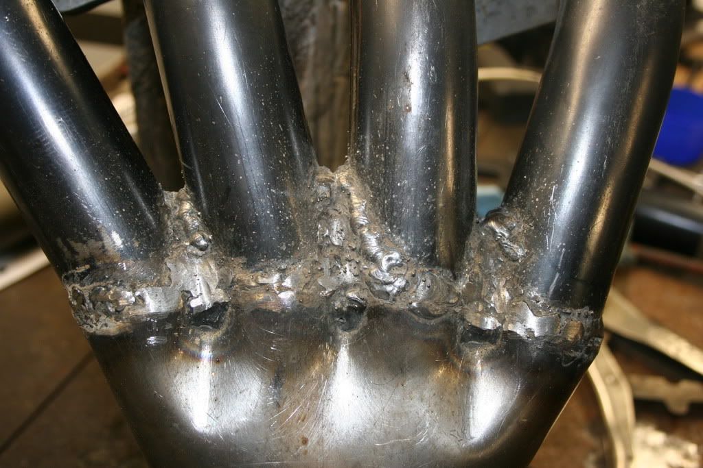
Note how much the weld in the webs have grown. I had welded the tubes together prior to inserting them into the collector, but I still had major leaks. I had to build the weld up that much in order to get the proper angle on the weld to get a decent seal.
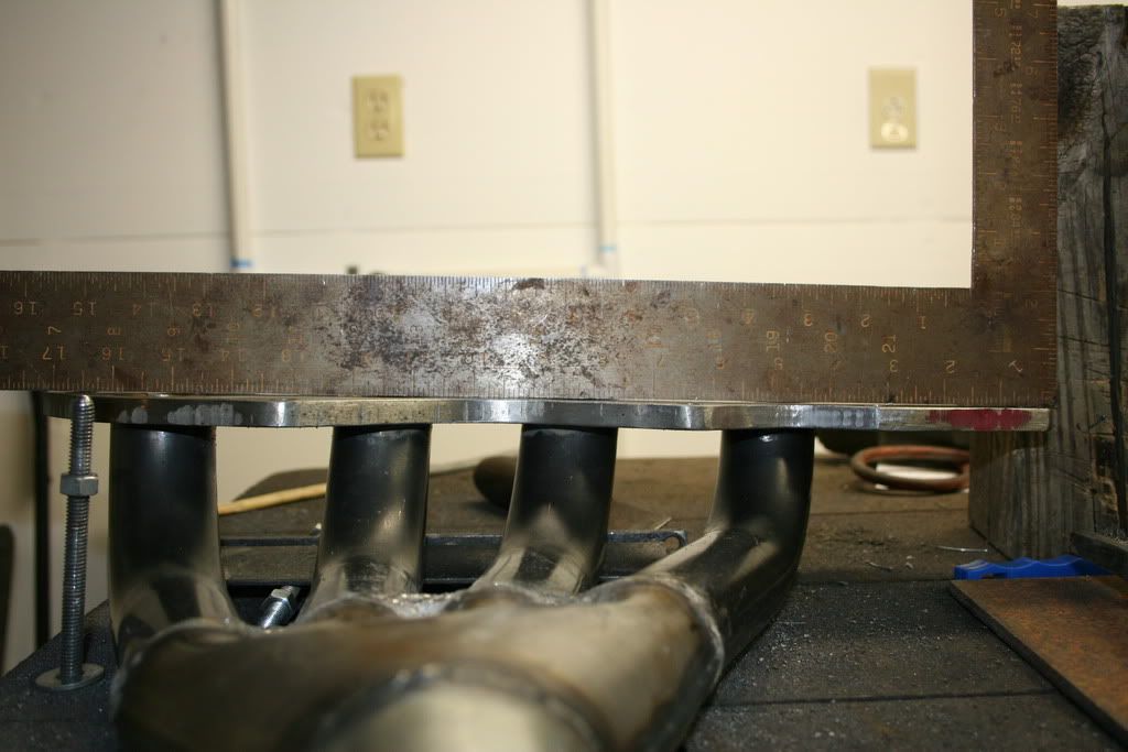
Next up, test for header flange flatness, big failure as can be seen:
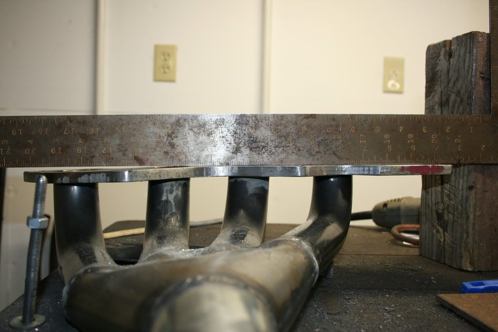
Note huge gap between the square and flange on the left side. Way too much to clean up. I don't know if this was caused by welding or if the steel was already warped, I did not test it prior to this point. By the way, I tested the square against a granite surface plate, it is flat. Cannot see any light between the square and plate. This is an old Craftsman square that has seen considerable use but has not been mistreated.
Anyway, time to put the "bim" to the header flange. I do not have any sort of press, so used my milling machine table.
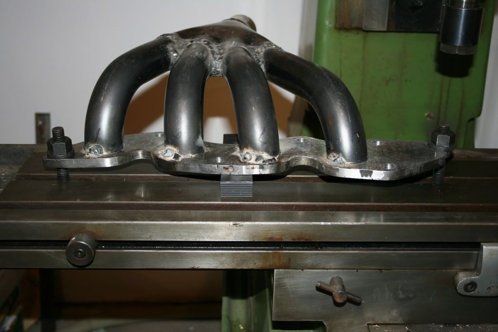
The funny looking thing under the middle of the header is a hold down clamp, being used as a spacer. It took a bout half a dozen tries of adding pressure with the bolts, removing and testing with the square before I saw this:
As you can see, it is pretty flat but not perfect, so I cleaned it up on a 6X48" belt sander. I think it is flat to within a couple of thou and the gasket should take care of that.
Bill
Note how much the weld in the webs have grown. I had welded the tubes together prior to inserting them into the collector, but I still had major leaks. I had to build the weld up that much in order to get the proper angle on the weld to get a decent seal.
Next up, test for header flange flatness, big failure as can be seen:
Note huge gap between the square and flange on the left side. Way too much to clean up. I don't know if this was caused by welding or if the steel was already warped, I did not test it prior to this point. By the way, I tested the square against a granite surface plate, it is flat. Cannot see any light between the square and plate. This is an old Craftsman square that has seen considerable use but has not been mistreated.
Anyway, time to put the "bim" to the header flange. I do not have any sort of press, so used my milling machine table.
The funny looking thing under the middle of the header is a hold down clamp, being used as a spacer. It took a bout half a dozen tries of adding pressure with the bolts, removing and testing with the square before I saw this:
As you can see, it is pretty flat but not perfect, so I cleaned it up on a 6X48" belt sander. I think it is flat to within a couple of thou and the gasket should take care of that.
Bill
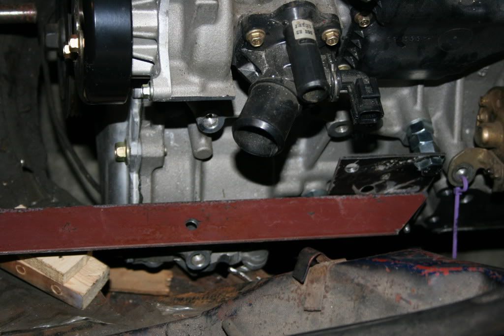
Here is the header installed. It just barely clears the inner tie rod and upper cruciform. I think that I will wait for the final installation in the good car to make some final adjustments, whatever they may be.
Don't see any way the alternator will fit in front of the header. It will have to go on the other side on in front of the engine.
Time to move on to the motor mounts. Connersville is not exactly the center of the motoring universe, especially upscale imported cars, so it looks like I will have to settle for 2.0 Pinto mounts. They are very close to what I think I will need and cheap, but have a funny looking cable with a clamp attached to it.
http://www.partsamerica.com/ProductDetail.aspx?MfrCode=ANH&MfrPartNumber=2363&PartType=27&PTSet=A
Anyone have any idea what that is for or what happens if it is removed? That is the mount I used on the Pinto engine and the clamp is a major PIA. I'm thinking it is used to properly orient the mount.
Bill
Bill seems like a lot of splatter on the tubes to flange weld compared to the 4 to 1 weld. You run out of gas or is there some sort of coating on the tubes?
There is a black coating on the tubes, have no idea what it is, although it seems to splatter. The guy at the local muffler shop said the bends I am using welds pretty good. The 4 to 1 weld is the only weld I have made that was not full of splatter. Damned if I know why. I am using flux core wire.
Bill
Mike, I'm afraid that at the least, that is putting the cart before the horse as I am going to spend the least amount possible, at least until the swap is road proven. It is going to cost a lot in time, but I have a lot of that and its value on the market is at an all time low.
So all in all, I think I will stand pat. I have no use for eye candy. I am planning on imposing upon Jarrid for engine control. The Duratec is good for way over 200 hp, so I do not need stronger internals. As it sets, it should be good for 150 hp, perhaps more and that should be plenty for me. If it comes up lacking, it will probably be because of the intake manifold and I can make up another one for fifty bucks. I sincerely doubt that any of their exhaust items will fit. Same with intake manifolds, with the possible exception of dual Weber intakes. I want Webers almost as much as I desire a case of the clap. As I think about it, perhaps even less. Besides, they would probably cost as much as the entire swap.
I could use a water rail, but damn, not at that price.
Bill