bobw
Donation Time
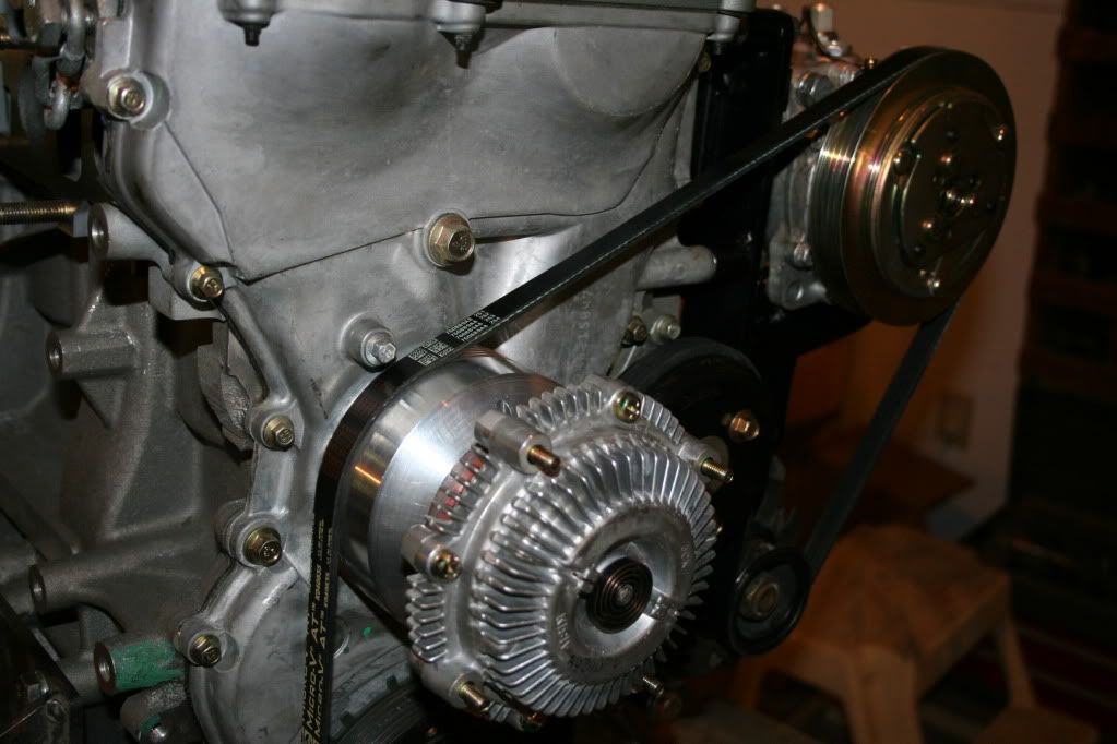
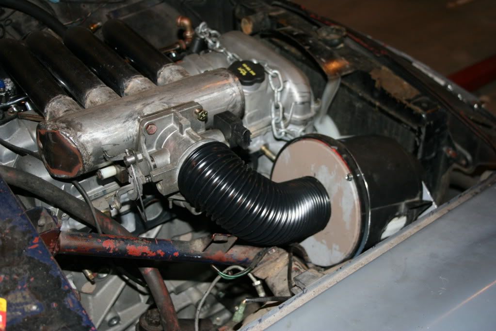
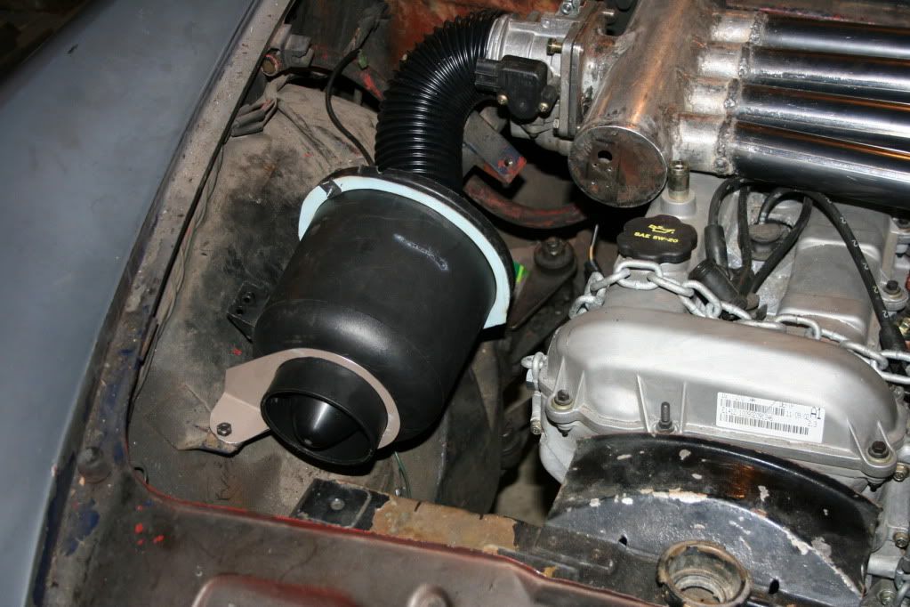
Sweet, I like the IDA intake with EFI air doors.
Hope you plan a good engine management system, one that knows how to do leading and trailing spark.
I'm using the same engine controller I used in my airplane. It's an EC2 from Real World Solutions. http://www.rotaryaviation.com/ It remains to be seen how well it will work in the auto application since it's usually set up for a prop load and 75-100% power operating range. They have been used in other auto applications, but I don't know how they worked out. Leading and trailing plugs are fired simeltaneously. I can always change to Megasquirt or something else if it doesn't work well.
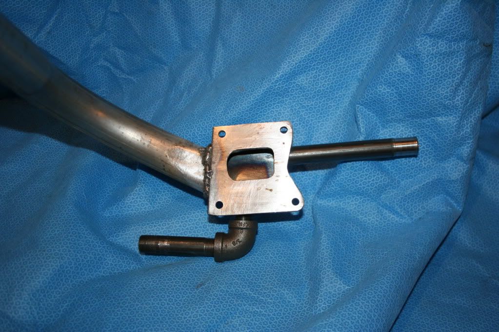
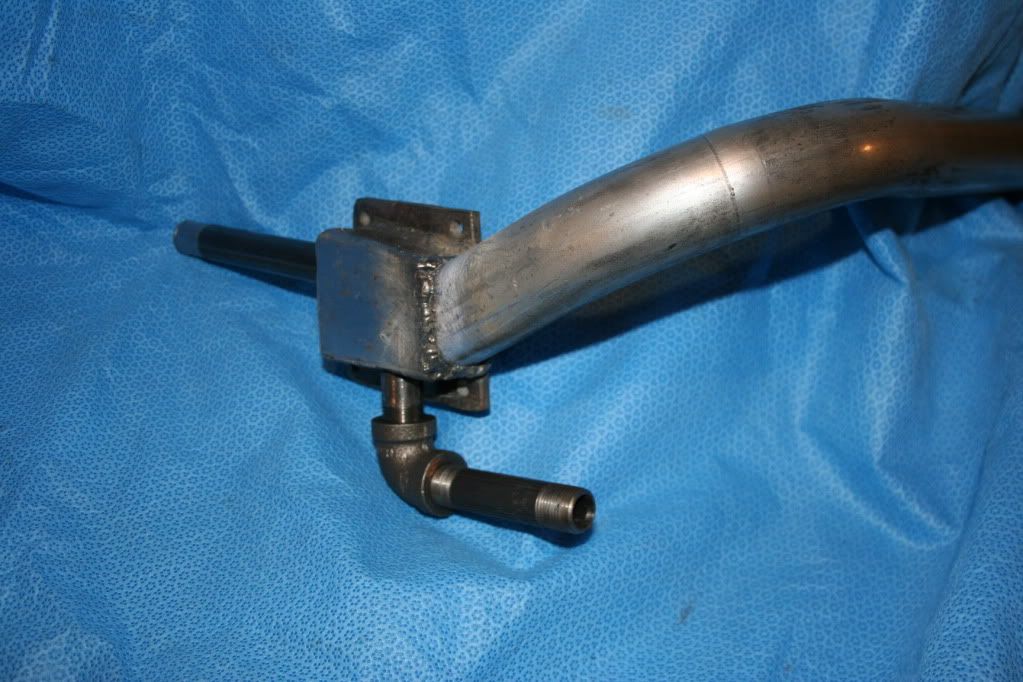
What's an air door? The intake manifold and throttle bodies were from Tweakit it Australia. The only EFI setup I could find off the shelf that would fit.
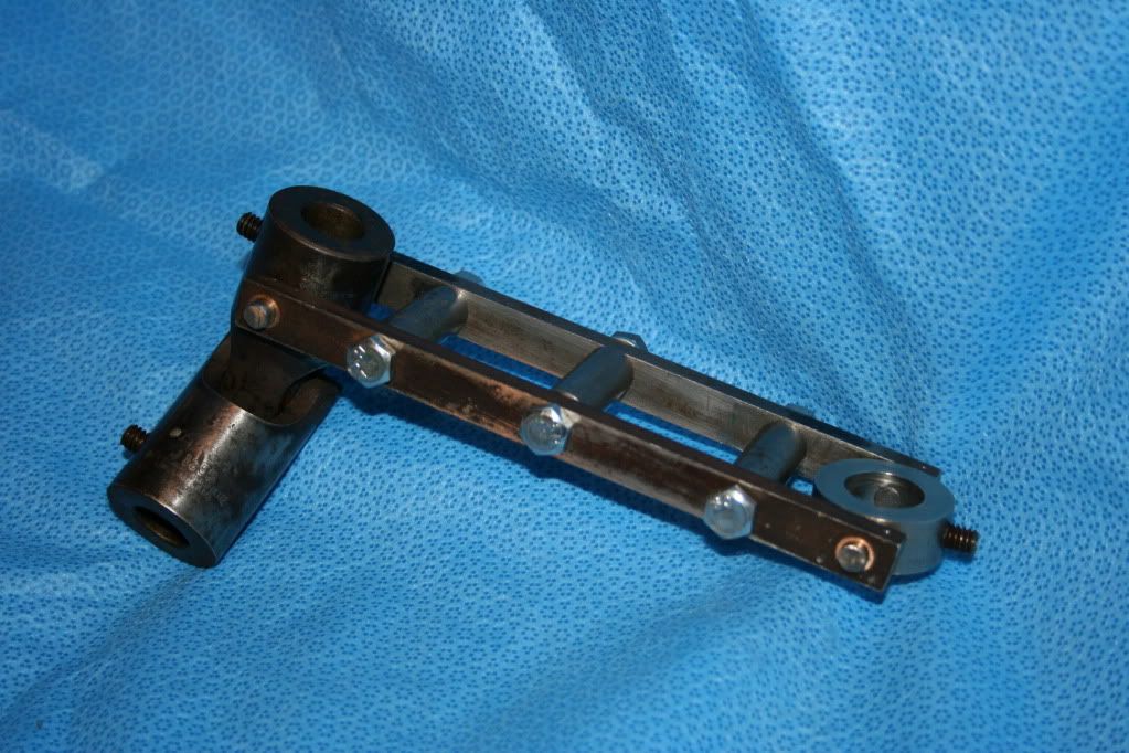
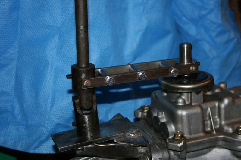
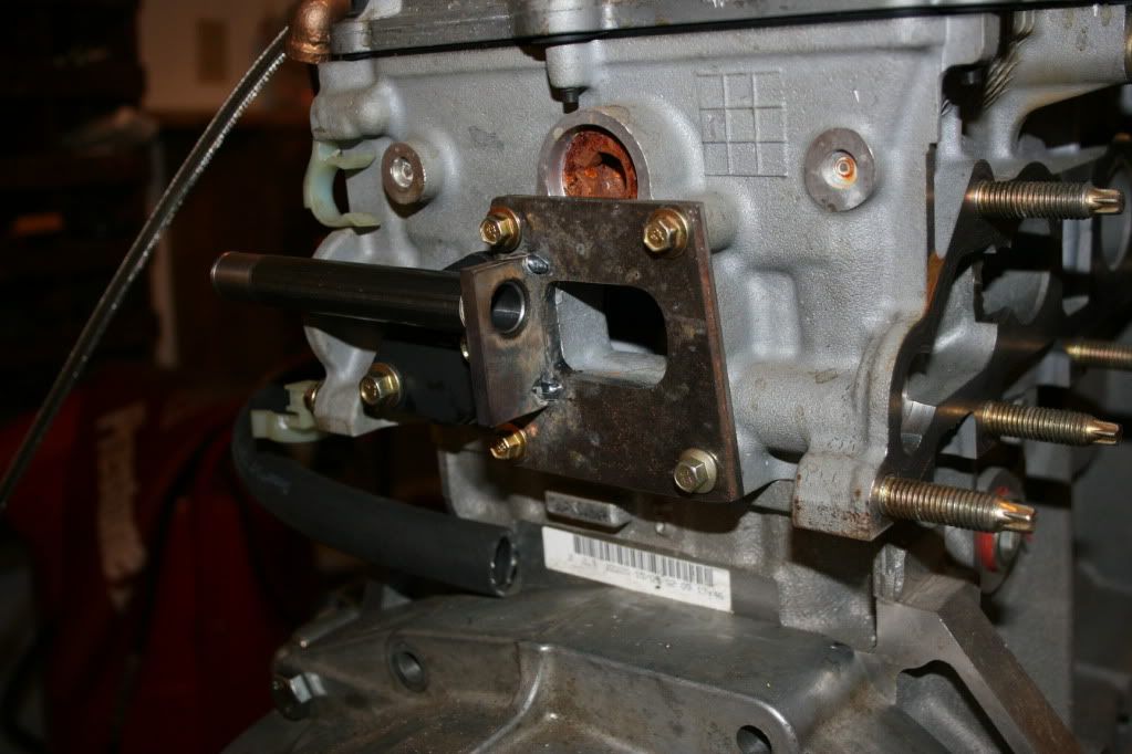
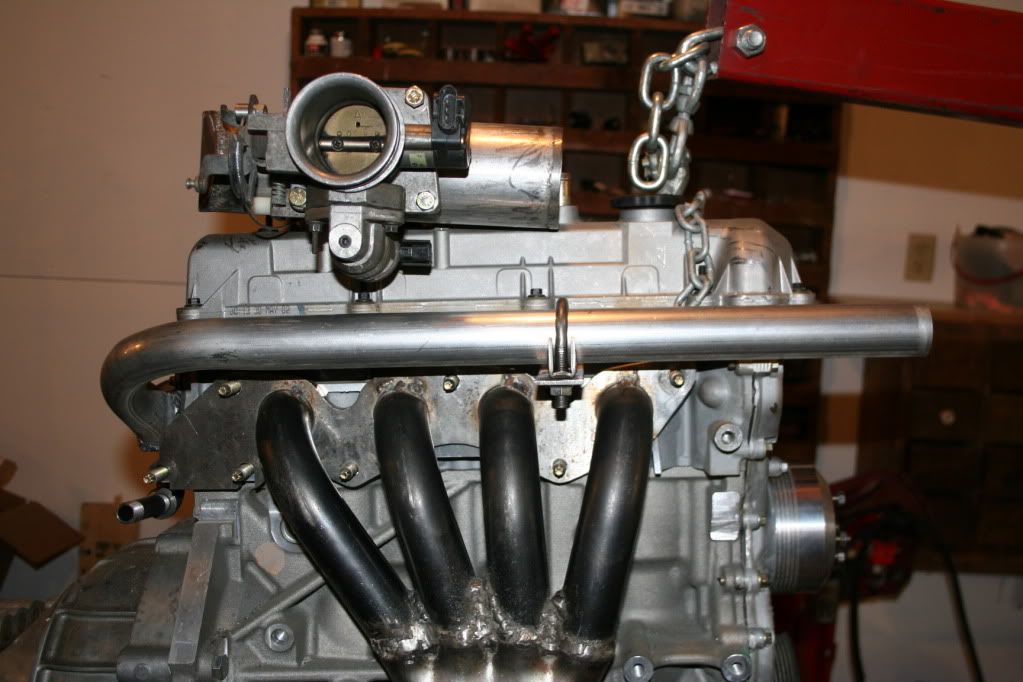
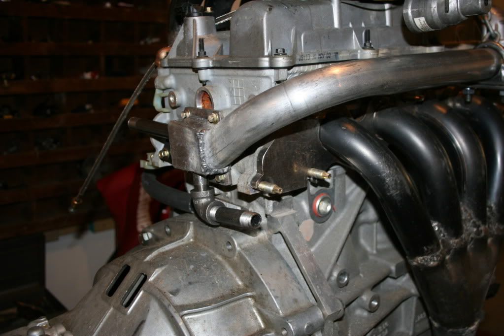
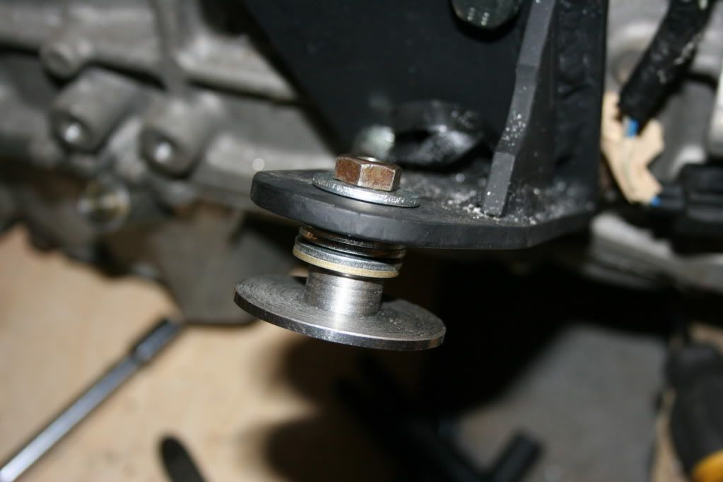
That's an interesting approach to the problem, never thought about doing it that way. I really like the linear pull. Keeps things lined up nicely. My setup requires some ticklish positioning of the cable in order to avoid excessive cable pressure against the cable sheath. It would help if the distance between the arm and cable holder was an inch or so greater, but there just isn't the room. Each installation presents its own problems. One (only?) advantage of my gizmo is the ease with which the ratio can be changed. I decided on a set of dimensions but drilled alternate holes, just in case. Turns out I needed them.
Bill, the first thing I noticed in your pictures was the adjustment holes. That's the first time I though about the linkage lengths being a problem.
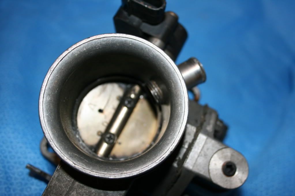
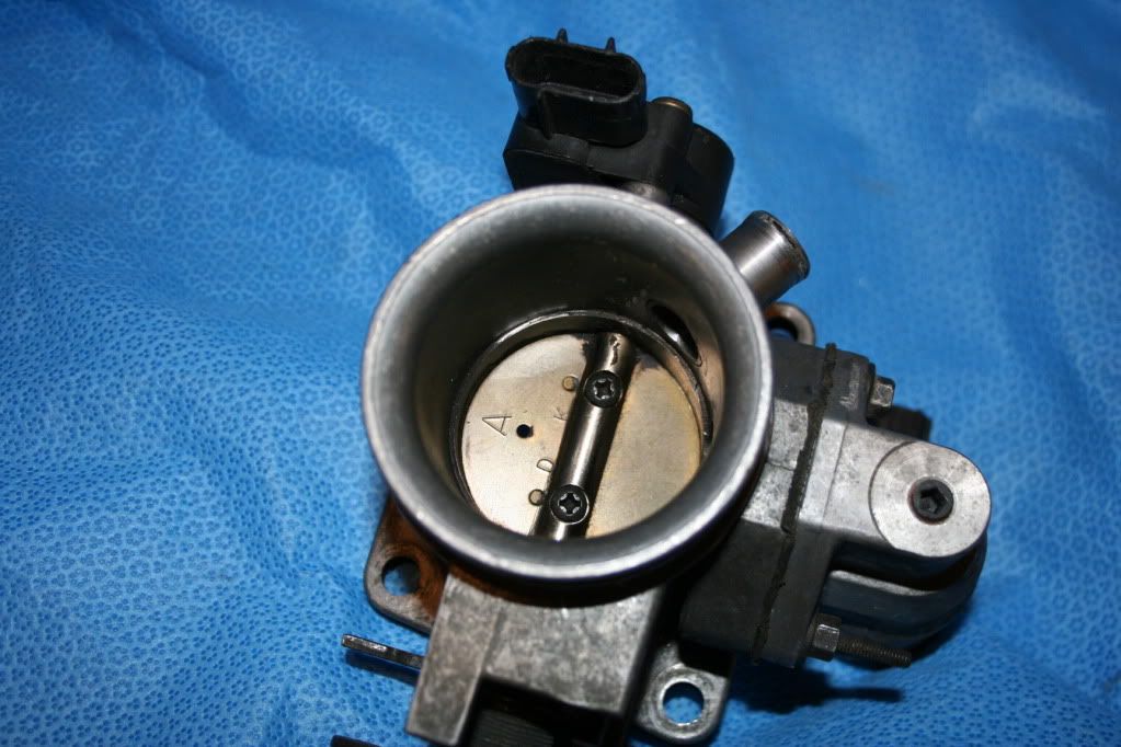
") I may need to add an extra return spring also. It seems like the throttle plate doesn't always want to close completely. I'm still playing with the adjustments.
I may need to add an extra return spring also. It seems like the throttle plate doesn't always want to close completely. I'm still playing with the adjustments.Bob W.