• Welcome to the new SAOCA website. Already a member? Simply click Log In/Sign Up up and to the right and use your same username and password from the old site. If you've forgotten your password, please send an email to membership@sunbeamalpine.org for assistance.

    If you're new here, click Log In/Sign Up and enter your information. We'll approve your account as quickly as possible, typically in about 24 hours. If it takes longer, you were probably caught in our spam/scam filter.

    Enjoy.

DuraPine II

Barry

Diamond Level Sponsor
Barry, thanks a big bunch for not only valaditing but correcting my thought plan. Your response is exactly the reason for my post. I look at it this way, .113" is 1/32" less than .145". A measurable improvement. I think I will do .100" offset, leaving .150" sidewall. How much do you suppose that compromises the strength of the arm? Should I be even more conservative? Maybe install a strap from mounting hole to mounting hole?

Bill


Bill,

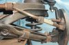
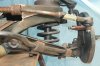
The critical area is the mounting hole that is closest to the tie-rod hole because that section of the steering arm is under the most bending load. The mounting hole farthest away from the tie-rod hole is under very little load.

Think I would offset the mounting hole closest to the tie-rod hole by about 1/16" and go for about 1/8" to 3/16" on the mounting hole farthest away from the tie-rod hole. Good flat washers that completely cover the "flats" and "slots" would certainly help and a strap from mounting hole to mounting hole would certainly not hurt anything.
 

260Alpine

Silver Level Sponsor
Yes, Good catch! Not mine, but he was in prototype fitting when we told him they were out of phase.
 

DanR

Diamond Level Sponsor
It was a complete Toyota unit from inside the engine compartment up to the steering wheel in the Silver Alpine
 

MikeH

Diamond Level Sponsor
Shouldn't your U joints be in phase?
I believe I understand what you mean by “in phase”, but why is it necessary with the steering shaft? Looking this up, it seems that the out of phase would only impact a spinning driveshaft, adding vibration.
 

Barry

Diamond Level Sponsor
Bill,

I am still having trouble visualizing the relationships between the crossmember, the steering rack, the tie-rods and the lower A-arms.

A picture from the front covering the full width from spindle-to-spindle would be very useful. From center line to spindle (either side or both) might show more detail.
 
Last edited:

Bill Blue

Platinum Level Sponsor
Barry, here 'ya go.

The rack is centered on the steering unit. The r&p unit is centered on the cross member. Suspension at full droop. The tie rod ends can be rotated up 1/2". The rack is setting at installed height.

Dig the notch fill pieces. I wanted a 3" X 1/8" angle iron, which they don't make. So the local iron monger said she could could bend one up out of 11 ga. steel. So she did. 3 X 3 X .120" - 29" long, twenty bucks. She inherited a 100 y.o. business philosophy that all customers are important and treated equally. It works for me.

BillIMG_6635.JPG
 

260Alpine

Silver Level Sponsor
Bill, Are the steering arms and tie rod ends going to be swapped to come down from top? At mid travel should be close to same angle as the bottom A arm.
 
Last edited:

Bill Blue

Platinum Level Sponsor
Bill, Are the steering arms and tie rod ends going to be swapped to come down from top? At mid travel should be close to same angle as the bottom A arm.
It's hard to see, but the tie rod ends are on the bottom of the arms. I was hoping the fill flash would make things more visible. Perhaps it did, just not enough.
Bill
 

260Alpine

Silver Level Sponsor
Bill, I see that, but to me it looks like they would be closer the other way. Also are you going to rotate the steering stub up? It would be good if both Ujoints were close to same angle.
 

Bill Blue

Platinum Level Sponsor
If the rod ends are on top, the rack would have to be raised an inch in order for the tie rods to be parallel with the lower A arm. With them on the bottom, the rod ends have to be raised a half inch to meet the parallel requirement. The steering arms have been modified to raise the rod ends. I have no idea what would have to be modified in order to raise the rack 1 inch. The steering stub will be rotated up as much as possible without raising the rack further or notching the cross member. There isn't much room between the rack and the cross member.

Bill
 

Barry

Diamond Level Sponsor
Barry, here 'ya go.

The rack is centered on the steering unit. The r&p unit is centered on the cross member. Suspension at full droop. The tie rod ends can be rotated up 1/2". The rack is setting at installed height.

Dig the notch fill pieces. I wanted a 3" X 1/8" angle iron, which they don't make. So the local iron monger said she could could bend one up out of 11 ga. steel. So she did. 3 X 3 X .120" - 29" long, twenty bucks. She inherited a 100 y.o. business philosophy that all customers are important and treated equally. It works for me.

BillView attachment 20671


Bill,

I took the liberty of drawing some lines on the picture you posted.

upload_2020-8-12_13-41-28.jpeg


The light blue line represents the inner pivot-to-ball joint line for the lower A-arm.

The yellow line represents the tie-rod with the tie-rod joint above the steering arm.

The red line represents the tie-rod with the tie-rod joint below the steering arm.​

The steering rack is a little "cattywampus" in the picture, but it is pretty clear that the yellow line (tie-rod line with tie-rod joint above the steering arm) is pretty much parallel with the light blue line (inner pivot-to-ball joint line for the lower A-arm) and the red line (tie-rod with the tie-rod joint below the steering arm) is nowhere close to being parallel with anything.

If the bellows will clear the "frame rails" at full suspension compression, the "tie-rod joints above the steering arms" layout looks good to me.
 

Bill Blue

Platinum Level Sponsor
I think I see my error. I was aligning the tie rod with the upper surface of the A arm instead of the light blue line. Will re-check.

Bill
 

Bill Blue

Platinum Level Sponsor
I attached the tie rods to the rod end. Leveled the rack with the sway bar and took a picture. Swapped the arm right to left and turned them upside down, then attached the tie rods to the rod end. Took another picture.

The suspension and arms are in full droop.

Bill
 

Attachments

  • IMG_6639.JPG
    IMG_6639.JPG
    250.7 KB · Views: 55
  • IMG_6638.JPG
    IMG_6638.JPG
    234.3 KB · Views: 56

260Alpine

Silver Level Sponsor
Bill, I think that looks much closer, but the bend in the tie rod is down intsead of straight forward. Rack to tie rod end has to be in a straight line. All pivot to pivot.
 
Last edited:

260Alpine

Silver Level Sponsor
Bill, With tie rod end on top can you slot the arms to go down a little or raise the rack a little?
 
Top