
-
Welcome to the new SAOCA website. Already a member? Simply click Log In/Sign Up up and to the right and use your same username and password from the old site. If you've forgotten your password, please send an email to membership@sunbeamalpine.org for assistance.
If you're new here, click Log In/Sign Up and enter your information. We'll approve your account as quickly as possible, typically in about 24 hours. If it takes longer, you were probably caught in our spam/scam filter.
Enjoy.
You are using an out of date browser. It may not display this or other websites correctly.
You should upgrade or use an alternative browser.
You should upgrade or use an alternative browser.
Starting issue
- Thread starter Acollin
- Start date
Ken Ellis
Donation Time
A few years ago, I implemented the cold-start circuit using a relay instead of direct connection. I don't remember exactly why, but it could be something like "the starter terminal is grounded when not activated". I'm not saying that is specifically the case, but there was some reason I opted for the relay solution. Or, the "reason" was a figment of my imagination and Mike's way is the best way!
(In thinking about this, I went to the color wiring diagram link I have stored on my phone, and found out it's hosted on Photobucket, which as we know is not long for this world. If copyright allows, we should move that image to this site so it's hosted locally if not already done. I'll end up saving jpeg in my phone.)
(In thinking about this, I went to the color wiring diagram link I have stored on my phone, and found out it's hosted on Photobucket, which as we know is not long for this world. If copyright allows, we should move that image to this site so it's hosted locally if not already done. I'll end up saving jpeg in my phone.)
Ken, Mike, Andrew
DUH ! Ken has described exactly why you cannot wire the green / white wire directly to the Red /White at the solenoid. If you do wire it that way, trying to preserve the "cold start" feature without the extra contact, the starter will come on as soon as you turn the key to ON. Turning the key to ON applies power to the coil, thru the ballast resistor. And that green /white wire will carry the power to the red /white terminal on the solenoid, and the solenoid will come on and crank the starter.
I KNEW there was a reason they didn't wire it this way from the factory, but obviously my mind (and Mikes?) is getting weaker with age!
And Ken, note that the color wiring diagrams ARE hosted here on the site, under Tech Data > Electrical Components:
http://www.sunbeamalpine.org/downloads/wiring_diagrams/s5_diagram.pdf
Tom
I did a recent test (helping another forum member out with a wiring question) and I found continuity between the white+green connector and the white+red connector on the solenoid. I can double check the actual resistance there, but my conclusion was it is a hard wired connection between the two connectors.
Ken - Which colored wiring diagram do you have? Is it this one?
http://mhartman.net/files/sunbeam/Wiring-SV.pdf
I also have another wiring diagram with a black background.
I've been dropping docs onto this page to create a repository:
http://wp.mhartman.net/home/cars/sunbeam/alpine/info
Mike
Ken - Which colored wiring diagram do you have? Is it this one?
http://mhartman.net/files/sunbeam/Wiring-SV.pdf
I also have another wiring diagram with a black background.
I've been dropping docs onto this page to create a repository:
http://wp.mhartman.net/home/cars/sunbeam/alpine/info
Mike
Acollin
Donation Time
One step backward two steps forward.
Good news: I put the used selinoid ( non cold start) on my car and all is as you would expect. I disconnected green/ white. Started up just great!
Once I knew all was well, I set out trying to fix the offending part. I tried to " stake" first.
Bad news :As you probably guessed, I broke a tiny bit of the Bakelite ---does not seem that I did too much damage. I soldered the flag back on and then "artfully" dabbed some JB weld where the Bakelite once was. Not a bad looking repair if I do say so myself. I do not yet know if my soldering repair did the trick.
Is there any of testing this part without actually putting it back in the car? For now, I am pleased with the current state of affairs and I assume I have a spare if my selinoid breaks down again.
Thanks again for all the help--- I will not be attaching green/ white to red/white!!!
Andrew
Sandy, Oregon
Easy to test your repair, assuming the flag no longer wobbles:
1) Use a multimeter and see of you have continuity between the repaired flag and the mounting bracket
OR
2) use jumper cables and apply power (polarity does not matter) - one cable to the repaired flag and one cable to the mounting bracket. You should hear a definite clunk as the solenoid coil pulls the contacts in.
Tom
Acollin
Donation Time
According to your test: It appears as if my repair to the selinoid was successful. I used the jumper cable method-- heard the clunk and saw the button retract.
However,
Could this simply be reporting a "no change"? My old selinoid would start the car when I pushed the button. Seeing the button retract suggests to me that I might still need the button to start the car.
Know that I know near nothing about what I am trying to discuss here. My reactions are little more than a response to my observation. Button retracts when power applied to resoldered flag and mounting bracket.
If you would agree that my repair has been successful, I assume that before my repair, the electrical impulse would not have made it through the now repaired flag terminal-- true?
Have I made some sense here and repaired my old selinoid?
Thanks--- you guys are outstanding
Andrew
Andrew,
I am 99% sure that your solenoid is now repaired and will work in your car. You should understand what the solenoid does. It has an electromagnet coil inside that, when power is applied to it moves a plunger that closes large contacts that complete the circuit to your starter. The button is the end of that plunger and allows you to move the plunger manually in the event that a broken wire, or bad connection, or bad ground prevents power from getting to the coil. Since your problem was intermittent and you saw the loose flag connector, it seems highly likely that the problem you had was a bad connection between the flag and the electromagnet coil wire. Now that you have re-soldered that connection, it no longer wobbles, and it moves the plunger when power is applied, I have high confidence it is fixed.
There is a slight possibility that the problem is actually a bad contact at the end of the plunger, such that it only sometimes makes good contact. This is highly unlikely because your original description said that turning the key had no effect, not even the solenoid going "clunk".
Tom
I’m reading all these questions and responses hoping to figure out my problem, but so far I’m stumped. Here‘a my situation: ‘66 Alpine, electronic ignition, new fully-charged battery with clean connections, new starter, new 4 terminal solenoid with “I” connector empty (no cold start green wire). I get a single click when attempting to start. I’m stumped. Any ideas?
Ted Smith in northwestern Michigan
Ted Smith in northwestern Michigan
hartmandm,What kind of new starter solenoid did you get and how is it wired up?
Do you have an engine ground strap?
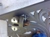
Thanks for your response. (See photos attached.) Starter cable attaches at the bottom of solenoid, positive battery cable attaches at the top, red/white ignition wire on the ”S” post closest to the battery input. Nothing on the “I” Post.
Where would I look for an engine ground strap. I’ve not seen one in years of tinkering.
Thanks again, Ted
Attachments

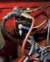
One more bit of input….. I’ve got 13v at the Battery posts and 13v at the battery cable post on the top of solenoid.hartmandm,
Thanks for your response. (See photos attached.) Starter cable attaches at the bottom of solenoid, positive battery cable attaches at the top, red/white ignition wire on the ”S” post closest to the battery input. Nothing on the “I” Post.
Where would I look for an engine ground strap. I’ve not seen one in years of tinkering.
Thanks again, Ted
I'm guessing the click you hear is the solenoid relay closing. Check the voltage at the solenoid post that goes to the starter with the ignition switch off and when the ignition switch is turned to "start". You should see no voltage with the ignition switch off and see battery voltage when the ignition switch is turned to "start".
The engine ground strap provides the path for electricity to flow from the engine assembly back to the chassis. The engine ground strap was originally installed around one of the gearbox mounts. People sometimes relocate the strap to another location, such as the bell housing. My car had the strap connected to the valve cover before I relocated it back to the gearbox mount. You can also check the resistance between a good metal contact point on the engine and the chassis or battery negative post. I believe it should be less than an ohm.

Mike
The engine ground strap provides the path for electricity to flow from the engine assembly back to the chassis. The engine ground strap was originally installed around one of the gearbox mounts. People sometimes relocate the strap to another location, such as the bell housing. My car had the strap connected to the valve cover before I relocated it back to the gearbox mount. You can also check the resistance between a good metal contact point on the engine and the chassis or battery negative post. I believe it should be less than an ohm.
Mike