• Welcome to the new SAOCA website. Already a member? Simply click Log In/Sign Up up and to the right and use your same username and password from the old site. If you've forgotten your password, please send an email to membership@sunbeamalpine.org for assistance.

    If you're new here, click Log In/Sign Up and enter your information. We'll approve your account as quickly as possible, typically in about 24 hours. If it takes longer, you were probably caught in our spam/scam filter.

    Enjoy.

Gas Tank Sending Unit Reisitance

RootesRacer

Donation Time
Jarrid,

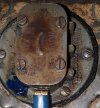
Since the Alpine gauges are based on resistive heating elements and bi-metal strips (unlike most gauges), knowing the gauge resistance and the sender resistance would allow calculating the series current at a given voltage.

Having said that, a chart of actual current vs. gauge reading would be very interesting. Confirmation that the fuel and temperature gauges exhibit the same response would also be nice to have.

The meters are too fast to be bi-metal.

Since they are also polarity insensitive, I suspect its a simple galvanometer with the counter field also produced by the impulse current.
 

Tom H

Platinum Level Sponsor
Series V gauges, using the Low, Mid, and Full cal dots for measuring:

Low - 34.9 mA (avg based on 4 gauges reading betw 33.6 and 36.3 mA)
MId - 78.0 mA (avg of 4 betw 76.4 and 80.5)
Full - 121.8 mA (avg of 4 betw 120 and 124)

Assuming a 10.8 volt source - (yes, 10.8, NOT 10.0) this correlates to sender resistances of
Low - 249 ohms
Mid - 77 ohms
Full - 28 Ohms

All 4 gauges were 61 ohms internally.

Note these values are cal values for achieving the cal points- the dots. Look at the dial to see what Temp or Gal is close to these points

Tom
 

Tom H

Platinum Level Sponsor
Series III, IV and V are bimetal. SI and II are apparently galvo. And Jarrid says polarity insensitive. So I guess they use a moving coil and a wound field magnet. Interesting. Or more likely they are like the MGA gauges described in the link Kevin provided earlier:

http://mgaguru.com/mgtech/electric/fg_03.htm

Tom
 

RootesRacer

Donation Time
OK here are the results I came up with:

Setup was with 4 precision wire wound 33.0 ohm resistors series and paralleled to specific resistor values as specified (since I didnt have a power rheostat).

"I total" was measured as the total meter current at the R sensor for that reading.
V total was 14.7v, "Temp displayed" is interpolated from gauge.

R sensor(ohms),Temp displayed (degF),I total(ma)
Infinite,90,52.8
132,98,79.4
99,106,84.6
66,114,92.8
33,154,105.5
22,180,112.0
16.5,190,116.0
8.25,228,123.5
0,245,130.0


Not sure what this proves, it looks like a 0 to 90 ohm (90 to 0 actually) might serve as a fail sensor range, though it doesnt fit terribly well.

I was planning on getting a 90-0 sender for my fuel cell, looks like I may need to add a bit of series resistance for it to show correctly on the high side.
 

RootesRacer

Donation Time
By measuring some voltages with an open and 8.25ohm sender resistance I did a basic circuit analysis (black box approach) and the circuit models as such:

VBat=14.7v
VSender open=9.0v
VSender with 8.25ohms=1.0v.


A polarity insensitive meter with one terminal terminal going to VBatt, which has a nominal resistance of 108 ohms. the meters other lead goes to the sender terminal.
Internally, there is a 170 ohm nominal resistance from the sender terminal to ground.

Meter "zero" current appears to me 52.8ma, with a 4.7v meter drop.
Meter "fullscale" current appears to be about 120ma with a 13.7v meter drop.


VBatt------[Meter 108ohms]---|SEND TERMINAL|---[170hms]--------GND.


Based on the resistance VS deflection data, it appears that a 100/6 (100ohms cold/empty, 6ohms hot/full) sensor type would be the most appropriate of the commonly used sender ranges for temperature and fuel level measurement.

As for meters voltage dependency, interestingly there is NOT a linear correlation in the fullscale sender resistance vs the displayed deflection.
With a 50% voltage reduction (7.8v), the meter deflection drops to about 75% needle deflection (200 deg from 230).
Therefore there must be some form of compensation as the result of the meters counter field generation mechanism.


Hope this was helpful to someone.


EDIT: FYI, the meter is "stamped in ink" 102/0, so perhaps thats the intended specified range of the sensor?
 

Tom H

Platinum Level Sponsor
Jarrid,

Nice work. I take from this, that the gauge design for the SI and SII is quite similar to the design shown in this article that Kevin posted earlier:

http://mgaguru.com/mgtech/electric/fg_01.htm

With several internal coils. Note however that the gauge in this article responds backwards from your decription (i.e. more resistance from sender means higher gauge reading) From the article and the diagram you can see how it is somewhat a Bridge circuit that reduces dependency on supply voltage.

And I assume the "Temp displayed" listed in your data was your best interpretation based on needle position and dial markings. But could you tell me what are the actual dial markings. I assume there is a value at Min, Mid and Max. And are there any tiny dots on the dial, likely cal points? If so, are any of these dots located at any of the data points you used. Note in the picture on the linked article there are little dots just below the scale arc on the dial.

Lastly, did you try a SI Fuel gauge? Is it the same, except for dial values? Same dots?

Tom
 

RootesRacer

Donation Time
Jarrid,

Nice work. I take from this, that the gauge design for the SI and SII is quite similar to the design shown in this article that Kevin posted earlier:

http://mgaguru.com/mgtech/electric/fg_01.htm

With several internal coils. Note however that the gauge in this article responds backwards from your decription (i.e. more resistance from sender means higher gauge reading) From the article and the diagram you can see how it is somewhat a Bridge circuit that reduces dependency on supply voltage.

And I assume the "Temp displayed" listed in your data was your best interpretation based on needle position and dial markings. But could you tell me what are the actual dial markings. I assume there is a value at Min, Mid and Max. And are there any tiny dots on the dial, likely cal points? If so, are any of these dots located at any of the data points you used. Note in the picture on the linked article there are little dots just below the scale arc on the dial.

Lastly, did you try a SI Fuel gauge? Is it the same, except for dial values? Same dots?

Tom

Tom,
The SII gauge (at least) is similar to the description of the MGAguro info, the resistances of the meter internals DO NOT JIVE. Nor does the meter config.
The MGA dwg also shows a 0 to 70 ohm sender range, the alpine clearly is higher.
The MGAguru schematic doesnt show the meter detail, it would be nice to know the details and the coil directions ETC, though this would be anecdotal.

I didnt read the article, I didnt want to bias myself.
If the MGA meter shows low with a low resistance, then yes, the sunbeam movement is reversed to the MGA function.

Since I didnt have a rheostat, I was only able to report the deflection points (in def F) for the specific resistances I could generate, so the data that you want, I cannot get. the resistances used were combinations of series and parallel resitors of 4 low TC 33.0ohm 3w resistors, which I had in a bin.

I have an SII, and I am unsure if the SI is exactly the same gauge. Since they have the same part# for the sender, I would think the gauges are functionally equiv at least.


Another interesting tidbit I failed to mention is that the wire in the meter movement coils, must have a hefty temperature coefficient, since the current through the meter would drop as it all heated up. The interesting thing was that although the current was dropping, the meters needle didnt move much. I cant explain it, must have something to do with the field generation losses canceling the armature losses but who knows...
 

Tom H

Platinum Level Sponsor
Jarrid, I understand that your resistor values limited the adjustability of your set up. So I assume your Temp readings were your best interpretation of the position on the dial at whatever resistance you applied- no problem. But just tell me what Temp numbers are on the dial. Are those numbers located with hash marks? At Min, Mid ,and Max, like shown on the MGA gauge? Or are they just located in a general area with no hash marks?

Thanks,

Tom
 

RootesRacer

Donation Time
Jarrid, I understand that your resistor values limited the adjustability of your set up. So I assume your Temp readings were your best interpretation of the position on the dial at whatever resistance you applied- no problem. But just tell me what Temp numbers are on the dial. Are those numbers located with hash marks? At Min, Mid ,and Max, like shown on the MGA gauge? Or are they just located in a general area with no hash marks?

Thanks,

Tom

The dial begins at 90, at about 35%FS it says 170, at about 70%FS it says 190 and at FS it says 230. Non linear as hell, must have a magnetic tweak to maximize range between 170 and 190.

There are tiny hash marks surrounding 90, at 50%FS and at FS.
 

DrNo

Donation Time
This is an old thread, but I'd like to add my $0.02-worth to what's here. I don't believe in telling people they're wrong unless I'm 100% sure I have my facts straight, so instead I'll just pass on what I know to be true from my own experience.

Some of the information above is the exact opposite of the setup in my SII. I have the original Jaeger 41L / 9gal(UK) gauge and a (possibly original) Smiths FT 5301/09 sender unit. I should mention that my car has been converted to negative Earth, but I believe this has no impact on the below...

The sender top plate is keyed to only fit one way around and has a clear "TOP" marking indicating the orientation (i.e. the Lucar connector points downwards) - see the attached picture. In this orientation, the sender reads 1 ohm when the arm is at the bottom of its stroke (i.e. tank empty) and 68 ohms when the arm is at the top of its stroke. Using a multimeter, it looks to me like the sender's rheostat is perfectly linear.

The Jaeger gauge used in the SI and SII cars is a magnetic type. These have two obvious characteristics: firstly, the needle gives an instant reading as soon as the ignition switch is turned on, and secondly, the reading mirrors the resistance of the sender unit: higher resistance = higher reading on the gauge (i.e. the gauge basically acts as an ohmmeter).

Using a simple spreadsheet, I came up with the following values for my SII:

Fuel (L)
(estimated)
Sender Resistance (Ω)Deflect Magnet
Current (A) @ 13.8V
Notes
Ignition offN/AN/ANeedle hard left (<0L)
0113.8Tank empty; needle at 0L
6101.4
12200.7
18300.5
24400.3
30500.3
36600.2
41680.2Tank full; needle just over 40L
No connectionInfinite (open circuit)0.0No connection; needle hard right (>40L)

Happy to be proven wrong... but this works for my car.
 

Attachments

  • SmithsSender.jpg
    SmithsSender.jpg
    567.6 KB · Views: 1

hartmandm

Moderator
Diamond Level Sponsor
The fuel sender is a 0 to 70 ohm range. Temp sender behavior is basically inverted to the fuel sender over a different resistance range.

Doc with more details is attached.

Mike
 

Attachments

  • fuel & temp gauges series 1&2 v1-1 inprog.pdf
    687.3 KB · Views: 13
Top