• Welcome to the new SAOCA website. Already a member? Simply click Log In/Sign Up up and to the right and use your same username and password from the old site. If you've forgotten your password, please send an email to membership@sunbeamalpine.org for assistance.

    If you're new here, click Log In/Sign Up and enter your information. We'll approve your account as quickly as possible, typically in about 24 hours. If it takes longer, you were probably caught in our spam/scam filter.

    Enjoy.

Fuel and Temp Gauge Wiring

Alpine James

Silver Level Sponsor
Hi All,

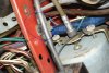
Just trying to finish my forever SV rewiring project. The wiring for the temp and fuel gauges seem straight forward but maybe not as obvious as I thought. Both gauges have 2 connectors with no indication which would be power and which would be sensor. I haven't been able to get the fuel gauge to read or even move ( I believe there is enough gas in the tank), and I haven't been able to warm the car up enough to get a reading on the temp gauge due to a carb leak that spills gas on the floor when running.

Wiring diagrams don't show anything definitive. Any thoughts?

Thanks, James
 

hartmandm

Moderator
Diamond Level Sponsor
Sounds like you have done rewiring. How have you wired them up currently?

The original circuit is basically:
Ignition "On" (12V) to fuse.
Fuse to voltage stabilizer.
Voltage stabilizer (10.8 / 10.0 V) to either connector on the gauge.
Connect other gauge connector to the sender.
Sender is then grounded.

The gauges have 61 ohms internal resistance. The amount of current flowing across the two connections on the gauge determines how far the gauge needle moves. The higher the resistance in the sender, the less the current flows, and the less the needle moves. The sender varies resistance from around 250 ohms (low) to 77 ohms (mid) to 28 ohms (high).

Mike
 
Last edited:

Alpine James

Silver Level Sponsor
Thanks,

So it doesn't matter which way the power and sensor wiring is done, so that should be OK.
Power is OK.
Gauges and voltage regulator are grounded.

So I will check the output of the regulator and the internal resistance of the gauges. Both gauges did work when the car last ran before I parked it.

Thanks, James
 

hartmandm

Moderator
Diamond Level Sponsor
It doesn't matter which direction the current flows through the gauge. The gauges work based on heating from the current flow.

If you have an original voltage stabilizer, it is grounded by its mounting screw. It needs to be mounted in a specific orientation. Tom H has a good test for the voltage regulator output using a test light. See this thread for info:
http://www.sunbeamalpine.org/forum/showthread.php?p=178074

Here's a photo of an original voltage stabilizer mounted. The mounting plate is aligned vertically. The stabilizer body is parallel to the ground.

FYI - Grounding the gauge housing is only relevant to the function of the internal light bulb.

Mike
 

Attachments

  • Capture.jpg
    Capture.jpg
    50.6 KB · Views: 53
Last edited:

Tom H

Platinum Level Sponsor
With the ignition ON ( maybe disconnect the coil so you don't overheat it) disconnect the wire from the temp sender and connect the wire to ground. If all is working reasonably well, the temp gauge should move to very high temperature ( full scale) rather quickly - maybe 20-30 seconds . Will not harm the gauge.

Same thing with the fuel sender, disconnect the wire from the fuel sender and connect the wire to ground. If the gauge moves to full scale, but not when the wire is connected to the sender, this indicates your system and wiring is OK but your fuel sender probably needs work. See other posts about fuel sender fixes.

If the gauge does not move when the wire is grounded then the problem is 1) wiring error , or 2) voltage stabilizer, or 3) gauge broken - unlikely.

Tom
 
Last edited:

Alpine James

Silver Level Sponsor
Hi All,

Thanks for the advice/tips. As it stands now, I am thinking it is the voltage regulator/stabilizer. 12V in but no output, and gauges seem to check out ok. However I will check using a test lamp.
What I find odd is that the regulator having to be mounted vertically. Is this some kind of liquid filled device?

Thanks, James
 

hartmandm

Moderator
Diamond Level Sponsor
No liquid. The voltage stabilizer is internally opening and closing at a frequency, causing the current to flow off and on. The cycling frequency results in an "average" voltage being produced, which is supposed to be 10.8 volts. The cycling is based on thermal heating / cooling of metal strips. The stabilizer orientation affects the cycling frequency.

Mike
 

Tom H

Platinum Level Sponsor
If there is no output voltage from the stabilizer, it's probably broken. But if it's a new solid state replacement type, it could be just a bad ground. If it is an original type the output will turn on/ off approximately 2 times per second.

You can check the rest of your system by putting a jumper wire from input to output on the stabilizer. That will cause the output to be full battery voltage and the gauges to read about 20 % high but they should work if all else is good.

Tom
 

hartmandm

Moderator
Diamond Level Sponsor
If you end up going with a solid state replacement for the voltage stabilizer, it will put out 10.0 volts. The temperature and fuel gauges will read slightly lower across their ranges than what they should be.

Mike
 

loose_electron

Donation Time
Getting the below "stabilizer" is the way to go if you are using original gauges for sure.

The original setup was prior to the widespread use of the transistor. Some of the hacks they used to make things work were creative.

As an electrical engineer re-wiring my S2 I have been doing a lot of re-design along the way. When I get done I will do a write-up on my suggested changes to make the electrical safer and more reliable.

New replacement solid state voltage stabilizer units are available from Moss Motors. Both positive and negative units are listed in their catalog. $14.99

https://mossmotors.com/solid-state-voltage-stabilizer-negative-ground?assoc=22966
 

Tom H

Platinum Level Sponsor
If the original stabilizer is bad, then replace it with a modern solid state one. I don't think they make the original type anymore anyhow.

BUT, if the old one is still working, In my opinion it's a better product than a solid state replacement. Think about it, 50 years later and it's still working! Some of that old technology is really great. I have done quite a bit of testing of these stabilizers and the gauges and found a couple things about the old design.
1) It switches on/off, using a heater and a bimetal strip to provide a constant voltage of about 10.8 RMS. The average output voltage is 10 V, but the real "heating value" of the output includes both the average or "DC" portion PLUS the on/OFF square wave "AC" portion. A solid state unit just puts out 10 V average, about 8% low.

2) Note that the 2 gauges this unit feeds also operate on a heater and bimetal principal. I think any shift in output due to ambient temperature changes is matched by similar change in the gauges.

I think the modern solid state units are fine and good enough for the application. But I do not see any advantage worth changing if the old one works.

Tom
 

Alpine James

Silver Level Sponsor
So I properly re-mounted the stabilizer on the dash rail and checked for voltage with both a meter and test light. 12V in but zero out and no reading on the fuel gauge. Ran a jumper from the alternate input to the stabilizer direct to the fuel gauge. This did give a reading. I then repeated with a second stabilizer (used) and had the same results. I am guessing both are faulty.

There is a possibility the stabilizer was bypassed when I bought the car a few years ago. The reason I am rewiring the car was the original was such a mess. So if a solid state unit will work then I will probably try that. Having a slightly erroneous reading on the fuel gauge isn't a real problem as long as I know it.

As far as the temp gauge goes, If the gauge reading is lower, would it be by 8%? This I could see being a bit of a problem.

Thanks, James
 

hartmandm

Moderator
Diamond Level Sponsor
You can compensate for the lower output of the solid state voltage stabilizer by adding a 500 ohm resistor in parallel to the sender. It won't make the readings accurate across the whole temperature range, but you can get the mid-point reading accurate. That should be sufficient for the temp gauge.

I'm working on documenting the details for adding the resistor in parallel as a compensation for the lower voltage. It may be a day or two before I have everything written up.

Mike
 

Alpine James

Silver Level Sponsor
So I fixed the carb leak and was able to run the engine till warm. No reading on the temp gauge until I wired direct to the regulator voltage input. Gauge then worked as I suspected and confirmed my suspicion of a faulty regulator. Good to know so now I can look for a replacement.

Thanks for the help and I look forward to reading any other fixes

James
 

Alpine James

Silver Level Sponsor
Hi all,
Found a replacement regulator locally, installed and checked fuel gauge. Appears to work fine. Will assume temp gauge will work as well.
Thanks for the tips.
James
 

hartmandm

Moderator
Diamond Level Sponsor
Glad to hear you have something working.

Sorry for my delay in providing an update. I want to setup a test bed and gather measurements for an original voltage stabilizer and a solid state stabilizer. Then I will be able to show a side-by-side comparison of the two, and also include options for adding some compensation for the solid state stabilizer's lower voltage. Likely will need a while to gather and document all of that data, especially with holiday demands.

Mike
 
Top