• Welcome to the new SAOCA website. Already a member? Simply click Log In/Sign Up up and to the right and use your same username and password from the old site. If you've forgotten your password, please send an email to membership@sunbeamalpine.org for assistance.

    If you're new here, click Log In/Sign Up and enter your information. We'll approve your account as quickly as possible, typically in about 24 hours. If it takes longer, you were probably caught in our spam/scam filter.

    Enjoy.

Duratec Installation

Bill Blue

Platinum Level Sponsor
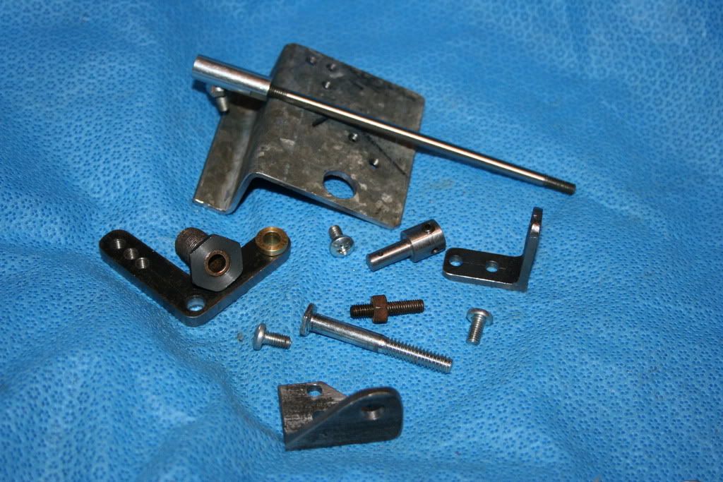
The little gizmo that is supposed to hold the accelerator cable in place is a small piece of black plastic that does not hold it securely. As I want to be sure nothing falls apart (like my current cable), I made another end. Here are the pieces:
IMG_0653.jpg

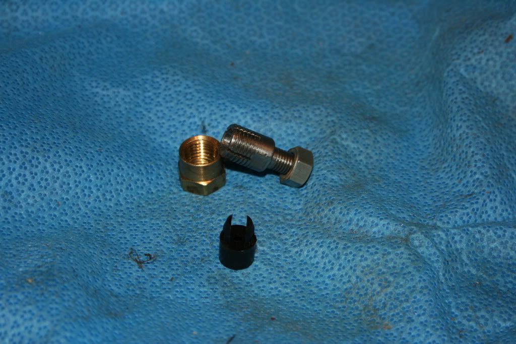
The black object is the holder that came with the kit. The brass object is a 1/4" brass pipe coupler with one end cut off. The steel "deally" is the holder. The large end is threaded 1/4" tapered pipe and the cable sheath slides into it, the other end is 5/16"-24.

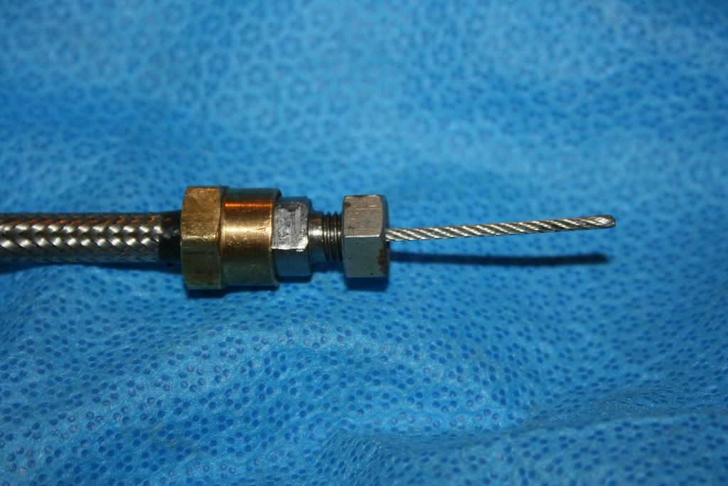
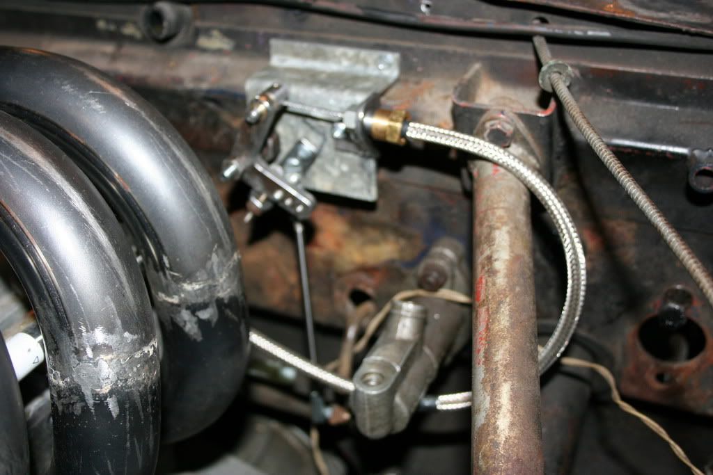
Here it is assembled. The tapered pipe thread clamps the "deally" onto the cable sheath pretty tightly. Sure is not going to fall out.
IMG_0654.jpg


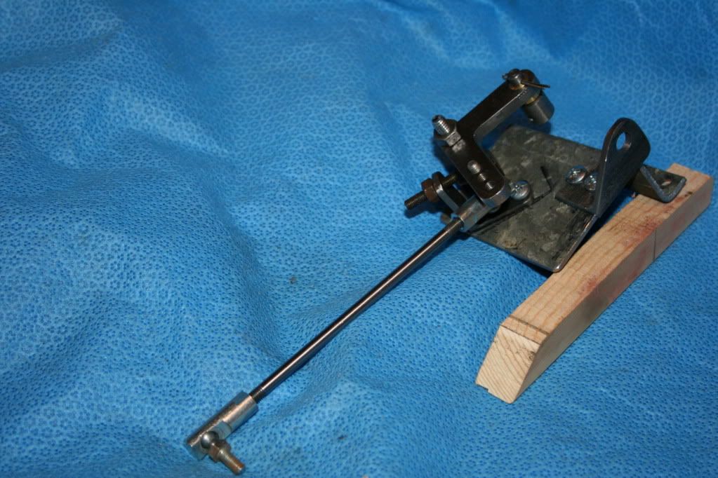
Onward to the accelerator cable bellcrank. Started with a piece of .100" galvanized stock I had laying around. There is nothing magic about the size of the piece, it was a handy sized scrap that I have hoarding for 20 years.
IMG_0655.jpg

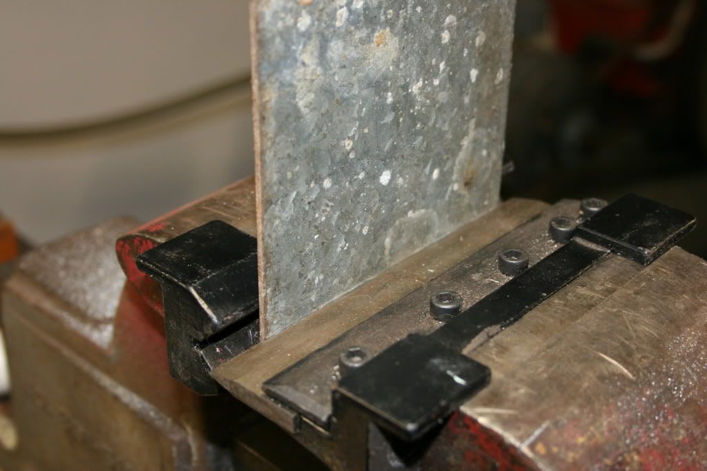
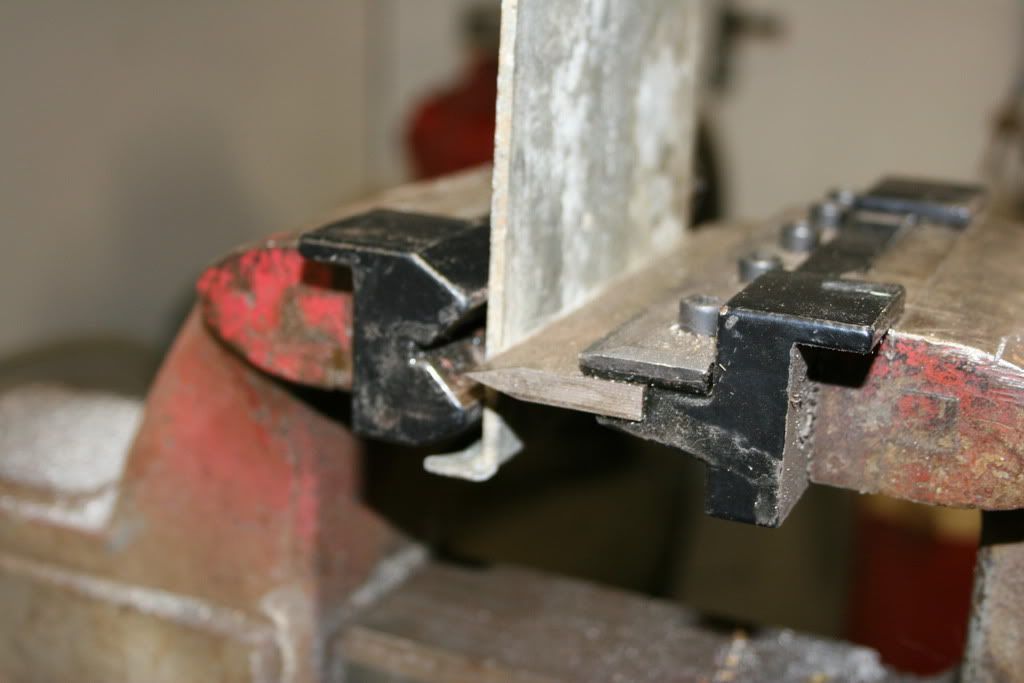
You can see the line that I scribed in order to get some sort of alignment. The tool being held in the vise is a neat little piece of Chinese rubber dog poo. It is held in the vise with strong magnets. Eat your heart out, Rick.

The finished bend. Automatically gives a 90* bend, will bend anything that you and your vise are capable of.
IMG_0656.jpg

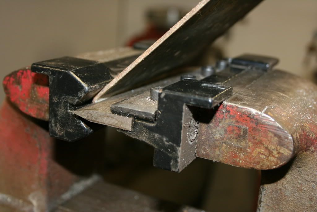
The blade is not hard, so round stock produces a nice cresent shaped ding. Don't ask.

Bill
 

Bill Blue

Platinum Level Sponsor
Set up for the second bend. Bends can be made pretty close to each other.
IMG_0657.jpg


All the parts for the bellcrank.
IMG_0659.jpg

Took many days of trial and error to determine the exact geometry of this thing. Actual construction is pretty simple. I decided to make bearings for all the working parts, it should last a loooong time. The large threaded part is an old 1/2-20 bolt cut to length. The 1/4-24 bolt slides into it and serves as the pivot point for the bell crank.
Here is the installation. Sorry for the fuzzy picture, cannot figure out how to over ride the auto focus. But I think you can see the vertical rod that transmits motion from the accelerator link to the bellcrank.
IMG_0662.jpg

The adjustable stop on the bellcrank adjusts pedal height.

Bill
 

MikeH

Diamond Level Sponsor
"The tool being held in the vise is a neat little piece of Chinese rubber dog poo. "

Where did you get that? Looks like something Harbour Freight might carry.
 

Bill Blue

Platinum Level Sponsor
Sorry guys. I looked at HF, Homier Distribution and Cummins Tools, can't find it. I'm pretty sure I got it at one of those, albeit maybe 5 years ago.

Maybe I should have my own auction?

Bill
 

Bill Blue

Platinum Level Sponsor
Here is a pic of the bell crank, ready to install. Sorry, but black does not show much detail. I have installed this on the Orange car to operate the Holley 32-36. Works very good. Should have made it a couple of years ago instead of the abortion I had been trying to use. Turns out that was a considerable amount of my carb "problems". I would adjust the cable, then something would slip or come out of adjustment.
img_0664.jpg


I decided to see if I could make some progress on the fan pulley. So I cut out some masonite and glued it up into a rough mockup.
img_0667.jpg


chucked it up by the I.D., even though it was rough, have to start somewhere.
img_0668.jpg

Turned the O.D. and faced off the end.

Then chucked it up by the O.D. and bored it to correct size.
img_0669.jpg

Then drilled the shaft hole. The main point of this exercise was to get an idea of the minimum I.D. I needed, there is not a lot of room and I do need room for a belt to run in grooves.
 

Bill Blue

Platinum Level Sponsor
The finished mock up.
img_0670.jpg

I set it aside and started to worry about other things. Gives me a chance to let the "opportunities" to sort of fester in my subconscious portion of the little brain. It needs all the help it can get.
 

bobw

Donation Time
Found one! http://www.amazon.com/Grizzly-H3245...f=sr_1_14?ie=UTF8&s=hi&qid=1236706380&sr=1-14
Interestingly, Grizzly doesn't list this on their site.

Jim,

I went to the grizzly.com and put vise brake in the search window"

http://grizzly.com/products/searchresults.aspx?q=vise brake

It came up with three versions, 4", 5", and 6". The 6" one seems to be the one listed on Amazon. This looks like a neat tool to have and I will definitely order one.


Bill,

I just found this thread, and I'm impressed with the design work you've done on this installation. I really appreciate the detailed photos of the various parts you've fabricated. It makes the efforts I've put forth doing an engine conversion look rather humble. :)

I have quite a different approach to my throttle cable adapter which isn't finished yet. I"m still waiting on a part to be fabricated. If it works, I will post some pictures. Otherwise, I will build one like yours.

Thanks,
Bob W.
 

Bill Blue

Platinum Level Sponsor
Bob, I'm glad you like my (maybe appreciate would be more appropriate) efforts. When I started this project I was hoping it would show guys what was needed to install a Duratec into an Alpine. It quickly became apparent the Duratec was not a good candidate for the swap, but I decided to go ahead and continue the thread. The intent of the thread is now multipurpose. I want to show it does not take incredible talent or deep pockets to put together a project and to give a first timer some insight into the challenges and perhaps some solutions. I hope it will stop some from jumping in over their heads, others the incentive and confidence to take the plunge. It certainly is not a showcase of workmanship. If it has, in some fashion, helped you along, that is my success.

May I ask, how is your project coming along? If there is anything I can do help you (or others) along with their project, let me know. That is especially true if some machine work may be involved in fabricating a part.

Bill
 

bobw

Donation Time
Hi Bill,

I have my engine installed. I still have to complete electrical, exhaust, and fuel supply. Then I should be able to drive the car. I will also be getting the exterior painted and a complete new interior, but won't be doing those myself.

A little history, I installed a rotary engine in an experimental aircraft a couple of years ago. Shortly after getting it flying I wrecked the airplane in a landing accident. There was a lot of damage to the aircraft and, fortunately, very little to me. After thinking it over for about 6 months, I decided to discontinue flying and keep my feet more or less on the ground.

Back about 25 years ago I had an Alpine, including 3 donor cars for spare parts, etc. After a whole series of problems with the running car (it wouldn't), I sold the whole lot of them. I was always a little sorry I did that. Anyway, I started looking around for an Alpine body I could put my rotary engine in. I found one that was in pretty good shape with no rust damage and here I am today.

I've done a couple of things that I would like to back up and do over. I may have to eventually but I consider this to be an ongoing project.

Bob W.
 

bobw

Donation Time
This is the throttle linkage I came up with. It seems to work OK, but the lengths didn't work out quite right so I don't quite get full open throttle. I will leave it for now until I find out how it runs.
med_p1000693.jpg


med_p1000694.jpg


Bob W.
 

Bill Blue

Platinum Level Sponsor
This is the throttle linkage I came up with. It seems to work OK, but the lengths didn't work out quite right so I don't quite get full open throttle.
Don't you just hate it when that happens?

That's an interesting approach to the problem, never thought about doing it that way. I really like the linear pull. Keeps things lined up nicely. My setup requires some ticklish positioning of the cable in order to avoid excessive cable pressure against the cable sheath. It would help if the distance between the arm and cable holder was an inch or so greater, but there just isn't the room. Each installation presents its own problems. One (only?) advantage of my gizmo is the ease with which the ratio can be changed. I decided on a set of dimensions but drilled alternate holes, just in case. Turns out I needed them.

I've done a couple of things that I would like to back up and do over. I may have to eventually but I consider this to be an ongoing project.

That, my friend, is the story of my life.

Bill
 
Top