One thing you are assuming here is that the original designer really knew his stuff and went to extremes to get everything right. I would say that this is a bad assumption just based on the fact that the thing is such a problem area. If you want to talk about bad engineering in a specific and first-year community college kind of way, the dump ports are square without radiused corners. The typical engineering school will teach this lesson over and over again starting in the first semester, while the physics you are talking about are at least semester 4...and the next regulator fixed this so it was likely an issue. I really don't think the guy that design this knew his stuff, or if he did, he was cutting corners.
The original design other than materials choice was pretty good, the design lasted more than 10 years.
I am unsure which specific OPR you are talking about, I only work with the late SV valves which have round dump holes, not square ones.
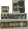
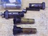
The materials issue is that Rootes used a mild steel for the body and a slightly harder steel for the piston. With time and rattle, the harder piston wore a step into the body around its nominal "control" zone and then one day, the piston hangs on the step in the body and you got near zero oil pressure.
This even happened with the latest 1725 designs so the updated OPR valve was not a fix at least for the hanging piston issue.
Had the piston been the softer and the body been harder, we probably would not be having this discussion.
You are right that a hard ball would cause wear into the ID of the cylinder. Unfortunately there is a balancing act going on because if the ball is too soft then the spring scratches it and the ball transfers those scratches to the inside of the cylinder causing even more wear. We have complete control over the cylinder material (within the limits of what can be machined at that size anyway). We have some control over the ball material; I'm pretty sure you can get aluminum balls in most every size and you can certainly get 304 (relatively soft by SS standards). The spring material we are sort of stuck with unless we want to spend $500 on a custom run of 50 springs. That means that the perfect design would have a ball harder than the spring and a tube the same hardness as the ball...possible with the right tooling, heat treating equipment, and rockwell tester, not possible with my setup. I'd like to make this myself but if push comes to shove I could job it out.
There are lots of springs available off the shelf, there is no need to get custom springs made when you have control over the piston diameter and the dump hole positions.
If I was making a body, I would use 4130 prehard which will not require heat treat afterwords as 35 rockwell would be plenty hard for the body.
A ball for the piston would be fine as even if it rattles, the spherical shape will not catch on the wear zone. As I said before, body wear will just result in a slow reduction in low RPM oil pressure due to piston leakby.
Even brass would be fine as a piston material but a brass cylinder will wear better than a brass ball.
Just getting the square piston profile out of the equation is a solution to the true problem. That said a chamfered or radiused piston of any material would probably yield a result that will never fail again.
I've only had physics 1 and statics so far. My understanding of resonant frequencies is that 1.) You almost have to try to get something that is actually destructive. 2.) In a system where forces are applied like this, the only way to change the resonant frequency is to change one of the forces (the oil pressure variation on one end, the spring on the other). Based on these I'd think that increasing the travel would not increase the dampening, and since the flow rate and oil pumps remain the same the only real change from stock to the ball design is the spring used. Maybe when I take physics 2 I'll learn that one or both of these is only correct in basic calculations.
I think that the oil pressure will not significantly effect resonance because the oil will be mostly uncoupled from the piston/spring mass at the point of dump.
Increasing the required piston travel to cause a flow increase means a reduction in mechanical gain. An infinite mechanical gain for instance would be moving the piston an infinitesimal distance into the dump orifice would cause an infinite amount of flow. A closed loop (feedback) mechanical system with high mechanical gain is likley to oscillate because the control lags the stimulus due to inertial effects. How high of gain is too high? I know the electrical analogue for gain phase shift products, but I am not a mechanical engineer. I do know it all comes down to damping ratios being is a certain band.
One other thing maybe you could explain...as far as the oil is concerned, a restriction is a restriction. A round, flat, or convex faced restriction will all be the same. When a ball moves to a point about 0.0001" past the radius it begins to release some tiny bit of oil. The same is true for a piston that has moved 0.0001" past it's face. At 0.01", 0.1", or 0.25" past the radius, wouldn't the oil released be the same (given the same release ports, spring, etc) as a piston that has moved 0.01", 0.1" or 0.25" past the face? If anything I'd think the other half of the ball being in the path of the oil would actually reduce the amount released a tiny bit by reducing the flow?
The radius of the ball will act differently as a valve compared to a flat piston moving into a dump port zone. The ball design has more flow paths than just straight into the dump zone and the smoother flow path will pass more oil than a flat piston does with the same cross-sectional area. Flow can exit the dump port from any direction with the same restrictivity due to the radius of the ball whereas with the flat piston, there is a step right at the interface between the flat of the piston and the dump port.
You say that designing this correctly would require iterative testing. You say this is because of the resonant frequency. The problem there is that you really can't...not without making the thing out of glass, putting it in a glass oil filter housing, mounting the whole engine on a stand, and using cameras or lasers to measure the frequency. Any equipment that would do it by pressure or vibration would be overwhelmed by the vibration of the whole engine or the pressure variances of the oil pump. You also wouldn't see it in the gauge because it would be faster than the stock variances and the gauge is designed with dampening to prevent it from showing those.
I say that I and probably you would need to iterate out a solution as neither of us probably knows enough about the oil fluid characteristics to be able to successfully model the design and go straight to metal.
I feel confident though that keeping the mechanical gain characteristics of the valve close by keeping the stock spring, similar piston mass and then experimenting with orifice size and progression would result in an acceptable result using the car as a test sled and not building a complex apparatus.
I simply could not assume that just putting in a more efficient valve into an otherwise stock setup would result in success without creating some new kind of problem. My years as an engineer has taught me this.