
-
Welcome to the new SAOCA website. Already a member? Simply click Log In/Sign Up up and to the right and use your same username and password from the old site. If you've forgotten your password, please send an email to membership@sunbeamalpine.org for assistance.
If you're new here, click Log In/Sign Up and enter your information. We'll approve your account as quickly as possible, typically in about 24 hours. If it takes longer, you were probably caught in our spam/scam filter.
Enjoy.
You are using an out of date browser. It may not display this or other websites correctly.
You should upgrade or use an alternative browser.
You should upgrade or use an alternative browser.
New instrument voltage stabilizer problems
- Thread starter cliffordalpine
- Start date
loose_electron
Donation Time
for what it is worth.. I have used Moss electronic units in several Alpines and Tigers that I own or have owned. I have not experienced any issues with them.
Yeah I suspect that something on the load side is sucking current, thus the suggested test of using a o.75A fuse to see if it blows, and then go from there.
There's not much inside these things, it's a 7810 voltage regulator and that's it. Built on the super cheap. They could have added some circuit protection stuff for another dollar so they never burn up, but self protect, cool off and re-start. But that would cost 50 cents that they did not want to spend.
Scotty
Silver Level Sponsor
Yeah I suspect that something on the load side is sucking current, thus the suggested test of using a o.75A fuse to see if it blows, and then go from there.
There's not much inside these things, it's a 7810 voltage regulator and that's it. Built on the super cheap. They could have added some circuit protection stuff for another dollar so they never burn up, but self protect, cool off and re-start. But that would cost 50 cents that they did not want to spend.
I feel like an idiot for asking this but how safe is our VS's? I had an old one that ran til it conked out, an old one that still works that I just updated and the new one from Rick which works fine. Is there a real risk of running these "stock" and how do we mitigate it? I just thought it might be some bad Chinese-made junk. There's a lot of that out there.
loose_electron
Donation Time
If this batch of VS’s are made in China, there’s your problem.
LOL!
Not so quick! In a prior life I dealt with a lot of Asia-Pacific manufacturing, and the trick there is to make sure that you got good quality control and device testing, and assembly inspections, in place. If you put all that in place you can get good quality assembly done there.
I do agree with you however. A lot of junk comes out of China assembly. You do need to hand hold and micro manage to get it right however.
loose_electron
Donation Time
I Is there a real risk of running these "stock" and how do we mitigate it? .
Generally when a 78XX voltage regulator burns out, the power transistor inside fails in an open condition. (it's a big NPN bipolar transistor, using semiconductor methods from around 1975 or so)
It there's a fuse feeding the device, you should be safe.
The 78XX voltage regulators have been around a long time and there are hundreds of millions of them in use.
AlsPine
Donation Time
Puzzling statement: You say "something other than tantalum ", but the next sentence says "Proper cap to use is tantalum" ?????.
I assume we would use something the neighborhood of 0.22 uF, so just use polystyrene or polyester caps.
Typically the input and output tantalum caps that are used on a voltage regulator are 4.7 to 10 uf at 35 volts.
Depending on the application, there might be a .1 uf ceramic disk cap in parallel with the tantalum cap. Also the tantalum caps are placed right at the regulator where the lead is soldered to the circuit board.
Al, I still don't understand these two sentences that say the opposite of each other
"They should have put something other than tantalum bypass caps on the input and output.
The proper caps to use are tantalum as they can handle the fast rise time of spikes."
Did you mean to say "they should have put something in addition to the tantalum bypass caps..." ? Or "they should have put something other than just the Tantalum...."
I'm not trying to nitpick, but I was totally confused by what you wrote, especially in view of what Berndt wrote about not using tantalum caps in automotive applications. I could not tell if you agreed with him or not. I have not heard of not using tantalum in auto applications; but then I never designed any products for auto applications.
The data sheet suggested in post #12 above shows/ suggests 0.22 uF be used on the inputs.
I still think that something is mis-wired, causing excess load on the Stabilizer,
Tom
bernd_st
Bronze Level Sponsor
Tom,
we do professionally design electronic components for cars that's why I mentioned about not to use tantalum caps for automotive applications. Lots a bad experiences from the past with them failing specifically under automotive stress so it became our design rule.
After there seems to be somewhat consensus about the need of a heat sink, the fundamental question still remains however whether the 7810 needs capacitance at the input/output for this specific application or not. I'ld agree with an earlier poster here that there are no sudden load changes in that application, but on the other hand caps would bring additional safety protection...
Last edited:
AlsPine
Donation Time
Al, I still don't understand these two sentences that say the opposite of each other
"They should have put something other than tantalum bypass caps on the input and output.
The proper caps to use are tantalum as they can handle the fast rise time of spikes."Tom
It means that since tantalum capacitors shouldn't be used in automotive applications, standard electrolytic capacitors are used instead.
Shannon Boal
Donation Time
How about this, the fuel gauge (or the temp gauge), is a little loose in it's mounting.....and sometimes the 10v terminal makes contact with the mounting bracket? This seems to me the likely location of an intermittent short.
Al, I'm still confused. Are you saying that in your sentence- "The proper caps to use are tantalum as they can handle the fast rise time of spikes" that you really meant to say - "the proper caps to use are standard electrolytics as they can handle the fast rise time of spikes" ???
Tom
Tom
loose_electron
Donation Time
It means that since tantalum capacitors shouldn't be used in automotive applications, standard electrolytic capacitors are used instead.
Electrolytic caps often have long term life issues. Each vendor is unique here, got to look at the expected life data.
I do agree that tantulum caps can fail.
Overvoltage spikes are often the root cause of that.
The method to protect against that would be using TVS diodes, and a small amount of series impedance (ferrite bead or RF choke, or small amount of resistance)
If you really need capacitiance in this scenario, I suggest ceramic capacitors with 35V or 50V max voltage rating. They exist up to 100uF, but for something like this 10uF/50V are cheap and readily available.
For this particular problem I don't see a need for using any capacitors.
If you stay under the rated current, I also don't see a need for a heat sink in most cases.
I'd agree with an earlier poster here that there are no sudden load changes in that application
Not sure this would meet the 'sudden load change' standard, but I have watched the resistance of a flaky fuel sender and with small movements of the float arm you can see the resistance ping pong multiple times per second between open circuit and the correct resistance. So maybe worst case that is about a 200 mA load change occurring multiple times per second.
OP indicated the regulators always smoked right after starting the car. I'd expect sporadic shorts to also occur while driving. I'm interested to see an update from the OP.
Mike
Shannon Boal
Donation Time
Shannon Boal
Donation Time
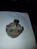
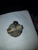
See the little bar? It is grounded. Now, a picture of the bar, in a crooked position:The fuel gauge (or the temp gauge), is a little loose in it's mounting.....and sometimes the 10v terminal makes This seems to me the likely location of an intermittent short. Here is a picture of a temp gauge
Attachments
Shannon Boal
Donation Time
So, there you have a hypothetical location for a short. Maybe stick a phone up there and take a photo?See the little bar? It is grounded. Now, a picture of the bar, in a crooked position:
loose_electron
Donation Time
So, there you have a hypothetical location for a short. Maybe stick a phone up there and take a photo?
The original poster hasn't been seen in awhile. Hopefully they solved the problem.
cliffordalpine
Gold Level Sponsor
thanks for your response as well as all of the others who added to my post...i took your advice and ordered aI'm not sure why you are burning up the Moss voltage stabilizers. Maybe the Moss voltage stabilizer isn't up to supplying the necessary amount of current in some scenarios. More current is required as the temp sender encounters higher coolant temps and the fuel tank sender is reading a full tank.
I don't see any capacitors in their design to help smooth things out, but not sure if that is really required. E.g. what if the fuel tank sender is a bit erratic and sometimes cycles between normal resistance and infinite resistance? I have a solid state voltage stabilizer from fellow Sunbeam owner Joe Parlanti (http://velocesolutionsllc.com/Voltage-Stabilzer-Stabilzer-1.htm) that I have used for a few years on my Series V. It appears to have a couple of capacitors under the shrink wrap.
Here are photos from the Moss site:
View attachment 25194
View attachment 25195
Picture above is of a positive ground item. But I assume the negative ground item also has "B" and "I" connectors and the housing is the ground connection.
I assume you have negative earth on your Alpine.
The voltage stabilizer is being grounded by its housing's mounting screw. Any chance the ground connection could be flaky?
The "B" connection is connected to a wire that is hot when the ignition switch is in the 'run' position.
The "I" connection goes to each of the fuel and temp gauges.
Here is the original series V circuit, which you are reproducing with your new wiring harness (possibly with a different fuse scheme...)
View attachment 25196
You can double check the gauges by removing the wires and measuring the resistance across the connectors on the gauges. You should see 61 ohms.
Mike
You may be seeing a brief voltage spike just after starting that cooks the voltage regulator.
I'd double check the gauges have 61 ohms resistance internally. If they do, then the current requirements shouldn't exceed 1 amp, even if the senders are ground faulted. E.g. 14.4 volts across 61 ohms is less than 250 mA.
Then I'd try a different solid state voltage stabilizer, such as the one from Joe Parlanti.
Mike
cliffordalpine
Gold Level Sponsor
thanks for your response as well as all of the others who added to my post...i took your advice and ordered a stabilizer from Joe Parlanti which is now installed and working great....I'm not sure why you are burning up the Moss voltage stabilizers. Maybe the Moss voltage stabilizer isn't up to supplying the necessary amount of current in some scenarios. More current is required as the temp sender encounters higher coolant temps and the fuel tank sender is reading a full tank.
I don't see any capacitors in their design to help smooth things out, but not sure if that is really required. E.g. what if the fuel tank sender is a bit erratic and sometimes cycles between normal resistance and infinite resistance? I have a solid state voltage stabilizer from fellow Sunbeam owner Joe Parlanti (http://velocesolutionsllc.com/Voltage-Stabilzer-Stabilzer-1.htm) that I have used for a few years on my Series V. It appears to have a couple of capacitors under the shrink wrap.
Here are photos from the Moss site:
View attachment 25194
View attachment 25195
Picture above is of a positive ground item. But I assume the negative ground item also has "B" and "I" connectors and the housing is the ground connection.
I assume you have negative earth on your Alpine.
The voltage stabilizer is being grounded by its housing's mounting screw. Any chance the ground connection could be flaky?
The "B" connection is connected to a wire that is hot when the ignition switch is in the 'run' position.
The "I" connection goes to each of the fuel and temp gauges.
Here is the original series V circuit, which you are reproducing with your new wiring harness (possibly with a different fuse scheme...)
View attachment 25196
You can double check the gauges by removing the wires and measuring the resistance across the connectors on the gauges. You should see 61 ohms.
Mike