• Welcome to the new SAOCA website. Already a member? Simply click Log In/Sign Up up and to the right and use your same username and password from the old site. If you've forgotten your password, please send an email to membership@sunbeamalpine.org for assistance.

    If you're new here, click Log In/Sign Up and enter your information. We'll approve your account as quickly as possible, typically in about 24 hours. If it takes longer, you were probably caught in our spam/scam filter.

    Enjoy.

Mazda Engine Swap

robertf

Donation Time
Thanks, it'll be a month or so before I'll get to mess with it again.

I was reasearching on what others have done to these engines as far as fuel and turbo goes, and it looks like the megasquirt is actually a decent enough controller that someone makes a plug and play kit (http://www.megasquirtpnp.com/)

Since I don't have much of the harness to start with there wasn't a point in getting the plug and play, so I went with the kit.

Lots of flying wires once you install the boost and fan control and modify it for the distributorless setup. The plugandplay kit is supposed to have a different board to fix that. It'll get covered in silicon, so I'm not too worried about it.
 

Attachments

  • ms3.jpg
    ms3.jpg
    89 KB · Views: 86
  • ms2.jpg
    ms2.jpg
    82.8 KB · Views: 55
  • ms1.jpg
    ms1.jpg
    88.1 KB · Views: 63

robertf

Donation Time
picked up another transmission and after a few hours of measuring and thinking it looks like a rube goldberg type shifter is the only way to make this work. I'll probably use an aftermarket t-5 shifter since they are cheap and easy to find and modify it to work.
 

Attachments

  • shifter2.jpg
    shifter2.jpg
    14.7 KB · Views: 98

Bill Blue

Platinum Level Sponsor
Could you explain your diagrams? Is the second one a remote, "Rube Goldberg" setup"?

If so, why keep the original shifter?

Bill
 

robertf

Donation Time
Could you explain your diagrams? Is the second one a remote, "Rube Goldberg" setup"?

If so, why keep the original shifter?

Bill


I'm not keeping the original shifter. Both pictures are of the same model which is my current plan for the remote shifter. Obviously the body/housing/mounting bracket ofr it is missing, but for modeling/testing the idea I'm not worried about that yet. Its in neutral in the first pic and first gear in the 2nd one to show how the linkage will work.

There is a high misalignment spherical bearing at one end of the square shaped linkage (shifter end), and a solid bushing at the other end, that lets the stock shift rod (the one on the top of the transmission model) to rotate about 30 degrees left and right, and then pushing the lever moves all the gizmos to shift it in or out.
 

robertf

Donation Time
Now you have me rethinking this.

This would use a stock t5 shifter and require the shifter coupling to be machined, but it's an easy piece and will probably end up being cheaper than misalignment bearings. Less moving parts and probably much less chance of binding.
 

Bill Blue

Platinum Level Sponsor
Now you have me rethinking this.

I sure am good, ain't I?

Seriously, have a question about the bottom ball/socket. If the ball was totally captured, wouldn't it bind? Looks like a small amount of vertical movement would be necessary. Am thinking that a smooth, hardened rod working in a Heim joint would work and be cheap.

Bill
 

robertf

Donation Time
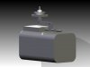
There is some vertical movement in the ball, its not completely captured and allowed to slide up and down. There is a plastic bushing that goes in there, don't really see a way around without breaking the rules of trig. The stock mazda shifter moved up and down quite a bit when shifted.


The heim joint/spherical bearing would be easy, but getting 30 degrees in each direction of travel out of heim joints isn't cheap after you factor in having to buy a much larger size bearing and misalignment bushings, and not having to modify the shifter is a bonus. As many off the shelf parts as possible is somewhat of a goal.

edit: If you are talking about orienting the axis of the spherical bearing inline with the shifter rod that might work, I'll have to see if there is enough travel for the up/down shifting (1st to 2nd, 3rd to 4th, 5th to reverse) for an off the shelf bearing, but its possible.
 

Bill Blue

Platinum Level Sponsor
After looking at the picture you posted of the stock transmission, looks to me like you are reversing the shift pattern, left to right. I think you will have first gear in the right hand side of the shift pattern.

Bill
 

robertf

Donation Time
Shift rail rotates opposite the shifter. Thats how all those go-fast short throw shifters are possible :D
 

Bill Blue

Platinum Level Sponsor
Okay, so you are duplicating the mechanism that's inside the shifter box. For some reason I got it in my head your mechanism reversed the rotation from stock, which I can now clearly see is not happening. Can we put that down as a brain fart?

Bill
 

robertf

Donation Time
changing the orientation of the spherical bearing worked. I need to get a t5 shifter to model it and finalize the design before building it, but I think this is the design I'll choose.

first pic is neutral, next is first gear.

edit: seems I've hit my storage quota, I'll put them on a hosting site later.
 

robertf

Donation Time
this is pretty close to how it will end up, but now I'm starting a few side projects before I finish this one. Bear with me on this, I'll be back to making progress on the Alpine soon.

I started thinking about how I would construct it. At first I thought about cutting it out and tig welding up some aluminum bar, but having a cast aluminum piece would be pretty slick. Project number 1: I've been wanting to do some low volume small sandcasting and this seems like the perfect project for it. Lightweight aluminum with only a few dimensionaly significant surfaces.

Sandcasting doesn't work too well without some decent molds, and what machine shop wouldn't laugh me out of the building if I told them my plan? Side project number two, a 3 axis CNC router to carve the molds.

Some MDF, 1/2" hardened rod, old printer parts, a rotozip, and a few more weekends and I should have it up and running.


shifter5.jpg


mill4.jpg


mill5.jpg


mill6.jpg
 

Ken Ellis

Donation Time
Now that you're halfway done (!), it might be fun to make/procure/kitbash a prototyping 'printer' to make up the part in curable resin, then make molds and cast from that model. That might have more uses in the car hobby than a dremel cnc setup. Unless you really want to make a dremel cnc setup... in which case, you're almost done!
 

robertf

Donation Time
They've got a few stereolithography machines here at A&M that do that, and I think I've seen a DIY one that used a glue gun but didn't pay much attention to it at the time.

I'll probably melt down a bunch of candles for prototype wax blocks before anything ridgid gets clamped down.

If it turns out nice enough then investment casting might be the way to go.
 

Bill Blue

Platinum Level Sponsor
I've been thinking about making a remote shifter for my Ranger M5. Am thinking of using a heim joint for the gearshift swivel joint instead of the ball socket. Does the heim not have the required range of movement for this type of application?

Bill
 

robertf

Donation Time
Been a while since I've got to work on this project

engine is almost in there. Working on the frame side of the engine mounts tonight and tomorrow night. Finished up the engine side mounts lastnight.

attachment.php


attachment.php


attachment.php
 

Bill Blue

Platinum Level Sponsor
What kind of mounts (pucks) are you using and what are the approximate dimensions?
Look like something I could use on the Duratec install.
Bill
 
Top