• Welcome to the new SAOCA website. Already a member? Simply click Log In/Sign Up up and to the right and use your same username and password from the old site. If you've forgotten your password, please send an email to membership@sunbeamalpine.org for assistance.

    If you're new here, click Log In/Sign Up and enter your information. We'll approve your account as quickly as possible, typically in about 24 hours. If it takes longer, you were probably caught in our spam/scam filter.

    Enjoy.

Fastback Alternator

Bill Blue

Platinum Level Sponsor
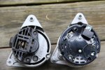
IMG_8312.JPGLost the input shaft nut on the alternator, ruined the alt fan and pulley. It seems all the rebuilt unit do not come with the pulley and fan. Found a new on Rock Auto. It arrived yesterday an looks very good and quite similar to the old one. Similar, but not exact. Different mount spacing and wiring is different. Different connectors (mostly size) and connector labels. I think I can fake the physical adaption and can attach any wire to any electrical terminal, except I don't have a clue which wire should go where, My only clue is the new alternator is internally regulated.
The terminals are identified as:
Old alternator
+
-
F-
IND
Appears to be wired into a Lucas component labelled "4TR Alternator Control"

New Alternator
B+
Blank
WL
WL
And W, this is located next to an opening with no terminal present
I suppose the "+" wire should go on the B+ terminal. And the IND wire is the dash light and stimulator, but where should it attach?
photos attached.
 

Bill Blue

Platinum Level Sponsor
Edit. The + and blank terminals are linked, I suppose to share the out load. WL probably stands for Warning Light, which probably needs to receive the IND connector. I think that should be enough to make the alternator operate, but should the Lucas Alternator be bypassed?
Bill
 

Shannon Boal

Platinum Level Sponsor
Edit. The + and blank terminals are linked, I suppose to share the out load. WL probably stands for Warning Light, which probably needs to receive the IND connector. I think that should be enough to make the alternator operate, but should the Lucas Alternator be bypassed?
Bill
Pretty sure the big spades, sharing load, are direct circuit to battery cable at solenoid. Guessing this unit energizes through warning lamp, (alpine had that odd warning lamp simulator circuit with relay) but I see two terminals on your alternator labeled that way, which is odd. I suggest wire it up as one-wire for a test, voltmeter measuring battery charging voltage, and use a common test light clipped to positive to test the WL energize function......I have a test bench for alternators, a pity we live so far apart!
 

Bill Blue

Platinum Level Sponsor
Yes, I'm pretty well convinced that is the way to approach this problem. My only question, will this "one wire" alternator work when fed through electronics designed to function as a voltage regulator, but not connected as such? I'm hoping that if it will not, the results will simply be no voltage, not a fire.

Bill
 

Shannon Boal

Platinum Level Sponsor
OK, going by the series V circuit, (I hope yours is the same); the warning lamp simulator is a relay that actuates the warning lamp when the stator quits producing AC voltage at a special tap on the stator. The lamp tells you that the belt may have broken, that you're fixin to have a dead battery or a hot motor. That is a good thing.
Your new alternator has two connections for WL.....maybe one is intended to load a lamp driven by 12V pos key-on voltage. Maybe the other is a stator tap producing that AC voltage for a relay.
What model alternator is the new one?
 

Shannon Boal

Platinum Level Sponsor
I would not think that the control box or relay from the old alternator would be any use here. I would start with direct connection of the two spades to the B+
 

Bill Blue

Platinum Level Sponsor
The alternator is a WAI 14029N. Lucas Type, made in India. Rated at 36 amps, but has a data performance sheet that indicates it is good for 45+ amps. Nicely made unit, a real looker.
My alternator control unit is solid state, no idea information. Looks like I can pull the wires going into the control unit and plug them into the Alternator. At least will give it a try. Well I cannot actually plug them into the alternator. Will need to make up jumper wires.
Bill
 
Top