• Welcome to the new SAOCA website. Already a member? Simply click Log In/Sign Up up and to the right and use your same username and password from the old site. If you've forgotten your password, please send an email to membership@sunbeamalpine.org for assistance.

    If you're new here, click Log In/Sign Up and enter your information. We'll approve your account as quickly as possible, typically in about 24 hours. If it takes longer, you were probably caught in our spam/scam filter.

    Enjoy.

Carbs and hoses - interference

woodybap

Silver Level Sponsor
Today was a good day. I have reached the point where the engine runs and the wheels turn. I was actually able to take the car off its jacks and motor around the neighborhood.

However there is still much under the hood that needs fixing. The 2 areas that need to be addressed are the carbs linkage and the layout of the hoses.

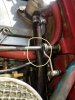
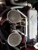
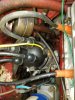
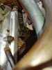
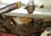
The mounting of the carbs looks homebrewed to me. The cross bar between the 2 carbs is held in place by a weird spring arrangement [Photo 4]. The ‘ball’ pulls out of the ‘socket” connection Photos 3 & 4]. Also the heater hose has worn a weak spot where it rests against the rear carb [Photo 6],

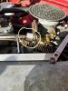
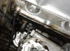
Moreover, the heater hose [red] and the hose that runs from the oil filler to the air cleaner [black] press against the throttle linkage [Photo 5].

Looking for suggestions on correcting these issues.

What style carbs are these anyway?
 

Attachments

  • Photo 4.jpg
    Photo 4.jpg
    280.8 KB · Views: 98
  • Photo 5.jpg
    Photo 5.jpg
    271.5 KB · Views: 96
  • Photo 3.jpg
    Photo 3.jpg
    395.4 KB · Views: 97
  • Photo 6.jpg
    Photo 6.jpg
    361.9 KB · Views: 94

RootesRacer

Donation Time
Yes, there is much going on there that is not stock.
The spring pulling your linkage does not belong, the newer aluminum pieces that links the valve cover also does not belong.
That looks like it was added to stiffen the carb intake, perhaps prev owner had intake vibrating loose issues.
You seem to have a PCV oil filler but those air cleaners are not the type used on PCV equipped engines.
You also lack the flame arrestor on the oil filer.
The carbs are zenith WIP-36, they would be correct for a SI - SII without PCV since they are the gauze type filters.
The PCV equipped engines used the batwing filters which provided filtered PCV air to the crankcase.
I'd be curious if you have a PCV type side cover and where those hoses are connected.

Not sure on the rubbing of the carb, I seem to recall there is supposed to be a hose retainer clamp at the far left upper housing screw.
Its been a long time since Ive seen a correct stock setup.
 

woodybap

Silver Level Sponsor
Yes, there is much going on there that is not stock.
The spring pulling your linkage does not belong, the newer aluminum pieces that links the valve cover also does not belong.
That looks like it was added to stiffen the carb intake, perhaps prev owner had intake vibrating loose issues.
You seem to have a PCV oil filler but those air cleaners are not the type used on PCV equipped engines.
You also lack the flame arrestor on the oil filer.
The carbs are zenith WIP-36, they would be correct for a SI - SII without PCV since they are the gauze type filters.
The PCV equipped engines used the batwing filters which provided filtered PCV air to the crankcase.
I'd be curious if you have a PCV type side cover and where those hoses are connected.

Not sure on the rubbing of the carb, I seem to recall there is supposed to be a hose retainer clamp at the far left upper housing screw.
Its been a long time since Ive seen a correct stock setup.


The body is SI with a 1725 so trying to go stock is not a viable option for me. Things do not match which results in a multiple, awkward, and binding hose arrangement. A better goal is to reconfigure what I have into a reliable fun car to drive.

Right now a hose goes [at an acute and crimping angle] from the tappet cover take off to the flame trap [which is tucked down low - Photo 245] and then to an engine petcock assembly on the driver’s side. A second hose goes from the oil filler take off to the air cleaner on the forward carb. It’s a mess.

Any specific ideas on what I can do to re-arrange/eliminate this mess so that there are not all these hoses converging and binding? No problem with buying some parts if need be.
 

Attachments

  • Photo 245.jpg
    Photo 245.jpg
    215.8 KB · Views: 44

RootesRacer

Donation Time
Your flame arrestor should be on the oil filler not on the side cover. Where is the clean air for the PCV coming from?
On the stock 1725 setup, fresh air comes from the 150CD air filters and then goes to the arrestor, which mounts to the oil filler.
The side cover goes to a hose that routes behind the engine and goes to the PCV valve.
Looks like yours is the reverse of this, which would still function provided that you have a PCV valve on the intake and you have clean air for the crankcase coming form somewhere.

The bigger issue though is that the early intake with those carbs was not jetted for PCV and will likley run lean at idle and light throttle.
 

woodybap

Silver Level Sponsor
Do not believe there is a PCV valve anywhere. The flame arrestor hose goes to the petcock shown in Photo 510. Where should the PCV be located? The ones I have seen in the past, in older American cars, were usually mounted into a grommet set into the valve cover.

So many questions and I appreciate your input and support. If I install a PCV between the carb intake and the oil filler, where could I get fresh air for the crankcase? Should I then just close off the opening by the tappet cover? Would I be better off just leaving things as is and do my best to re-route things?
 

Attachments

  • Photo 510.jpg
    Photo 510.jpg
    3.3 KB · Views: 29

RootesRacer

Donation Time
Your picture is too small to see anything relating to the PCV valve.
Only the SIII twin zenith intake had a PCV valve and like I said, it used a different air cleaner setup, not the gauze filters you have.
The PCV valve is on the intake. If you used your SI intake on the 1725, it will not have a PCV valve.

You still have the 1725 portions of the PCV system, which could be a problem.
If you dont have a PCV valve, your engine will start spewing oil since there is nowhere for the crank vapors to leave the engine and it will pressurize.

The SI to SIII engines without PCV used a vented oil filler cap (see 65beams picture above) and a side cover with a road tube that vents the crankcase vapors under the car.
 

65beam

Donation Time
It's fairly easy to set up a 1725 to make it work like the series 1 & 2 engines. It looks like you have the cover on the right side of the engine that was standard on the engine. There should be a small tube coming off the side cover to the rear of the distributor. It maybe two inches long and points up. The series 1 or 2 setup would have had a vent tube that turned down and vented the engine towards the road. You can do this by taking a piece of copper tubing about 2 1/2 feet long and bend it in a tight U shape. Use a short piece of hose slipped over the tube coming off the side cover and slip the bent tube into the hose. secure both with two small hose clamps. Now you have a road vent which won't hurt anything. Now take that flame trap and all the other pieces you removed to do this and put some where out of the way and forget you have them. The next thing you need is an oil filler tube and cap for a series 1 or 2. PM me if you need the correct oil cap. I have a bunch of them. They don't have any type of vent except for the oil fill cap. Check the photos of my red car and the photos of my white car I just posted. This eliminates all hoses on the carb side except for the heater hoses. The white car has a vacuum hose feeding the brake booster . Your series 1 should not have a booster. Notice that the heater hose is routed close to the valve cover. You don't need the braces or the front spring. The white car has one of the new 1725 engines with all series two parts on the engine. The dual Zenith carbs were used on series 1,2 and early series 3 Alpines. There was not a PCV. Hopes this helps.110_0722.JPG 110_0723.JPG 110_0671.JPG
 

beamdream

Gold Level Sponsor
These pics might also help.

Series 1 1600 correct throttle links, heater hose routing and engine draft tube into my home made oil catcher, and yes its rhd
 

Attachments

  • 20200106_194747.jpg
    20200106_194747.jpg
    259.9 KB · Views: 52
  • 20200106_194542.jpg
    20200106_194542.jpg
    265.2 KB · Views: 51

woodybap

Silver Level Sponsor
It's fairly easy to set up a 1725 to make it work like the series 1 & 2 engines. It looks like you have the cover on the right side of the engine that was standard on the engine. There should be a small tube coming off the side cover to the rear of the distributor. It maybe two inches long and points up. The series 1 or 2 setup would have had a vent tube that turned down and vented the engine towards the road. You can do this by taking a piece of copper tubing about 2 1/2 feet long and bend it in a tight U shape. Use a short piece of hose slipped over the tube coming off the side cover and slip the bent tube into the hose. secure both with two small hose clamps. Now you have a road vent which won't hurt anything. Now take that flame trap and all the other pieces you removed to do this and put some where out of the way and forget you have them. The next thing you need is an oil filler tube and cap for a series 1 or 2. PM me if you need the correct oil cap. I have a bunch of them. They don't have any type of vent except for the oil fill cap. Check the photos of my red car and the photos of my white car I just posted. This eliminates all hoses on the carb side except for the heater hoses. The white car has a vacuum hose feeding the brake booster . Your series 1 should not have a booster. Notice that the heater hose is routed close to the valve cover. You don't need the braces or the front spring. The white car has one of the new 1725 engines with all series two parts on the engine. The dual Zenith carbs were used on series 1,2 and early series 3 Alpines. There was not a PCV. Hopes this helps.View attachment 18472 View attachment 18473 View attachment 18474

Got it, I think. PMing you about the oil filler cap. Any idea on what to do about the petcock assembly [that the flame trap now hooks to] on the left side of the engine? See updated and enlarged photo.
 

Attachments

  • Petcock 510  .jpg
    Petcock 510 .jpg
    300.3 KB · Views: 35

RootesRacer

Donation Time
The place where you have a petcock was where raw fuel could drain from the intake past a check valve.
Its not where a PCV would be, most people just block that off with a pipe plug.

It sounds to me like converting to a road tube (no PCV) would be the easiest and most effective solution.
 

bernd_st

Bronze Level Sponsor
@beamdream : Your carbs are most likely S2 ones but not series 1. The return spring lower hook was not fixed to the exhaust manifold and the red coloured bush at the firewall holder looks weird to me...
 
Last edited:

beamdream

Gold Level Sponsor
@beamdream : Your carbs are most likely S2 ones but not series 1. The return spring lower lower hook was not fixed to the exhaust manifold and the red coloured bush at the firewall holder looks weird to me...

Thanks bernd, the carbs are a mix of WIA and WIP bits and pieces I have put together as it's almost impossible to find decent original carbs, the bush and return spring are also my own creations, it all works well and has done for many years.

My apologies to anyone who accepted my original comment about "correct throttle linkage" for a Series 1, I was in fact trying to portray a "typical" Series 1 with Zenith carbs, I have chastised myself and will pay more attention to any further inputs on future topics.
 

husky drvr

Platinum Level Sponsor
woodybap,

I noticed in the pic of the drain valve there appears to be the 1725 PCV valve installed between the valve body and the hose coming from the side cover. It appears that the OE PCV system IS installed in an unconventional manner. The execution of that installation could use a bit of "tweaking". I wonder if the drain hole in the manifold was enlarged to match the PCV airflow requirements?

It would also help if you could find an original linkage set for your carbs. It looks like your linkage might have some geometry issues and the OE socket is designed to accept a shaft with a machined ball and thin neck. It also has a pair of small holes aligned to accept a small cotter key that captures the ball in the socket. Later models could have used a deeper socket.

Good luck,
Don
 

bernd_st

Bronze Level Sponsor
Thanks bernd, the carbs are a mix of WIA and WIP bits and pieces I have put together as it's almost impossible to find decent original carbs, the bush and return spring are also my own creations, it all works well and has done for many years.

My apologies to anyone who accepted my original comment about "correct throttle linkage" for a Series 1, I was in fact trying to portray a "typical" Series 1 with Zenith carbs, I have chastised myself and will pay more attention to any further inputs on future topics.

Thanks for your comment - well understood. Just wanted to avoid members getting mislead. If there is any demand for used Zenith parts you may contact me...
 
Top