• Welcome to the new SAOCA website. Already a member? Simply click Log In/Sign Up up and to the right and use your same username and password from the old site. If you've forgotten your password, please send an email to membership@sunbeamalpine.org for assistance.

    If you're new here, click Log In/Sign Up and enter your information. We'll approve your account as quickly as possible, typically in about 24 hours. If it takes longer, you were probably caught in our spam/scam filter.

    Enjoy.

A solution in search of a problem

Barry

Diamond Level Sponsor
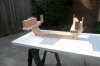
As noted in post # 18, the previous wooden mockup revealed a fatal design flaw, so a new and improved design (version III-B ???) was developed.

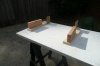
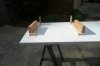
The first two pictures show "adapters" that will attach to the Alpine frame rails (represented by the vertical 2x4's) using the four standard crossmember attachment bolts.

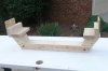
The next two pictures show the crossmember that will attach to the adapters.

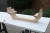
The last picture shows the combined adapters and crossmember.

More to come.
 

Attachments

  • P1010389 (Custom).JPG
    P1010389 (Custom).JPG
    56.2 KB · Views: 44
  • P1010388 (Custom).JPG
    P1010388 (Custom).JPG
    61.6 KB · Views: 32
  • P1010397 (Custom).JPG
    P1010397 (Custom).JPG
    66.9 KB · Views: 37
  • P1010398 (Custom).JPG
    P1010398 (Custom).JPG
    68.5 KB · Views: 34
  • P1010391 (Custom).JPG
    P1010391 (Custom).JPG
    72.2 KB · Views: 44

EriktheAwful

Donation Time
The upper control arm cross shafts are 5/8" coarse thread, but there really isn't enough thread to safely bolt circle track heim joints onto them, which is part of why I'll be custom making a cross member for mine. The lower control arm cross shafts are 11/16" coarse thread, and there aren't any readily available heim joints in that size, and especially none that will screw into 5/8" threaded sleeves.

Edit: Just realized this is a 3-page post. Looks very nice! Are you going to share plans when you are done? I noticed you're using a triangulated lower arm. Probably smarter than me. I'm using a stock-style MII lower arm and a tension rod.
 
Last edited:

Barry

Diamond Level Sponsor
Are you going to share plans when you are done? I noticed you're using a triangulated lower arm. Probably smarter than me. I'm using a stock-style MII lower arm and a tension rod.


Never say never, but providing plans is not a great business model.

There is no difference between the geometry of a triangulated lower arm and a stock-style lower arm with a strut rod if you have a suitable location to mount the "frame end" of the strut rod. Not sure where the strut rod would mount to the Alpine unibody. Note that a rear mounted strut rod is under compression (rather than tension) during braking, so keeping it "in column" is critical.
 

EriktheAwful

Donation Time
Sorry, I didn't realize you were planning some business on it.

My Alpine came pretty rough, so I have no problem welding brackets onto the frame for tension rods. I realize if they're in front they'll have to drop down pretty far to keep them nearly parallel, and they'll need a sizeable gusset. I hadn't really though about mounting them behind. Is there any reason I shouldn't?

Note - the wider the angle on your ball joint holder the easier it is to get clearance around coil overs.
 

Barry

Diamond Level Sponsor
Sorry, I didn't realize you were planning some business on it.

My Alpine came pretty rough, so I have no problem welding brackets onto the frame for tension rods. I realize if they're in front they'll have to drop down pretty far to keep them nearly parallel, and they'll need a sizeable gusset. I hadn't really though about mounting them behind. Is there any reason I shouldn't?

Note - the wider the angle on your ball joint holder the easier it is to get clearance around coil overs.


Erik,

The M-II had front mounted strut rods, but lots of "hot rod" adaptations move the struts to the rear. There is no difference in geometry as long as the strut pivot point is in line with the inner pivot point of the lower control arm. The Alpine "frame rails" drop sharply at the firewall, so rear mounted struts might work out.

Finding room for coil overs is one of the challenges of putting 10 pounds in a 5 pound bag.
 

Barry

Diamond Level Sponsor
The latest wooden mockup (version 5-something) is in the car.

At design ride height, the spindle is 13-1/2" below the top of the fender arch. With a 24" tire, the top of the fender arch is 1-1/2" above the top of the tire. I tried 1" above the top of the tire, but did not like the way it looked.

The best I can measure with a cheap gauge, the camber gain is 3 degrees at 3" of suspension compression (about +0.75 degree for the first inch, about 1.00 degree for the second inch and about 1.25 degree for the third inch).

At design ride height, the bottom of the crossmember is 5-1/2" above ground level. WSM 145 shows the ground clearance for a S-V as 4-1/2", so 5-1/2" under the crossmember should be plenty.

A factory S-V Alpine steel wheel (13") interferes with the lower ball joint; adding a 1/4" spacer almost eliminates the interference. A 14" steel wheel should be OK, but a 14" alloy wheel might be iffy. A 15" wheel clears by a mile. Upper ball joint clearance is not an issue. I don't have one to try, but it looks like a 15x7 or even 15x8 wheel should work.

Time to start building in steel.
 

Barry

Diamond Level Sponsor
So much for "time to build in steel".

The bad news is that I ran into a problem with the spindle / wheel / tire being about 1" too far forward.

The good news is that moving everything 1" to the rear appears to eliminate the problem with installing the rear crossmember attachment bolts and that means I should be able to eliminate the "adapter plates".

A new wooden mockup (Version 7-something ???) is ready for installation.

More problems and "solutions" to follow.
 

Bill Blue

Platinum Level Sponsor
Isn't it great to solve a problem, only to discover it was never a problem? How many times???? How many unnecessary prototypes can a man build?? The answer, my friend, is blowing in the wind.

Bill
 

EriktheAwful

Donation Time
Any updates? I'm interested in how it turns out, and will probably buy one if its priced reasonably and will get my Sunbeam project back on track.
 

Barry

Diamond Level Sponsor
Eric,

Lots of changes, a few improvements and lots of unsatisfactory (to me) results. The issue is how to provide mounting points for the upper a-arm and the top of the coil-over that provide adequate strength, do not interfere with anything and don't look like something out of a junkyard.

Did not think that anything on an Alpine could be too big, but the "inner fender" panels are too wide and get in the way.
 
Last edited:

Alpine66

Donation Time
Eric,

Lots of changes, a few improvements and lots of unsatisfactory (to me) results. The issue is how to provide mounting points for the upper a-arm and the top of the coil-over that provide adequate strength, do not interfere with anything and don't look like something out of a junkyard.

Did not think that anything on an Alpine could be too big, but the "inner fender" panels are too wide and get in the way.

Nothing a plasma cutter couldn't cure .....
 

Barry

Diamond Level Sponsor
Nothing a plasma cutter couldn't cure .....


That thought has crossed my mind on several occasions, but I started out with the goal of a "bolt on" installation with the stock unibody and I am still hopeful.
 

EriktheAwful

Donation Time
Have you considered drilling holes in the fenders and putting bolts through? Or is that going too far? When I was looking at off-the-shelf crossmembers, most went over the top of the framerails, but Fatman and one other had under-rail crossmembers that looked intriguing.
 
Top