• Welcome to the new SAOCA website. Already a member? Simply click Log In/Sign Up up and to the right and use your same username and password from the old site. If you've forgotten your password, please send an email to membership@sunbeamalpine.org for assistance.

    If you're new here, click Log In/Sign Up and enter your information. We'll approve your account as quickly as possible, typically in about 24 hours. If it takes longer, you were probably caught in our spam/scam filter.

    Enjoy.

Ed’s Solid State Gauge Regulator

mxp01

Platinum Level Sponsor
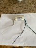
I’m currently installing a Rebel harness. Years ago I installed one of Ed Esslinger’s solid state gauge regulators. While pulling out the old harness I foolishly forgot to label the wires on his regulator. I have 3 color wires on it. Green, black, and white. Black and green are together on one side and white on the other side. I know others here have this same regulator. Can anyone help me out with identifying 12v feeding, ground and 10v to the gauges?

Thanks.
 

Attachments

  • image.jpg
    image.jpg
    300 KB · Views: 48

hartmandm

Moderator
Diamond Level Sponsor
Never seen one of those before. Only a guess based on the original harness colors:
White - 12V feed (i.e. ignition run wire)
Black - ground
Green - regulated 10V

Mike
 

sunalp

Diamond Level Sponsor
Don't forget that this is a gauge regulator. Stock ones have power in and the gauges coming out.
Seeing one wire is going in, my guess would be that was the power into the regulator with the colored
wires running to the fuel and temp gauges. You could just do a trial and error situation with a battery
charger powering the circuits(after disconnecting the battery to test this. That way you won't harm anything.
My 2 cents.
 

mxp01

Platinum Level Sponsor
Did/do the stock regulators have a terminal for ground Or just one 12v in with two 10v out? Looking at the SIV wiring diagram I do not see route for ground coming from the regulator. Did the original device ground on the surface it was mounted on (the dash mounting rail)?

The wiring digram does show two leads coming from the regulator to the gauges.
 

loose_electron

Donation Time
https://www.ti.com/lit/ds/slvs056p/slvs056p.pdf

What is inside that little box is most likely a 7810 voltage regulator.
Above link is the spec for that.

If I had to guess, White is output, Black is input and green is ground.

BUT that is just a guess. could be totally wrong.
If you can open up the package, you can trace it back, using the spec sheet I link to.
 

hartmandm

Moderator
Diamond Level Sponsor
Zooming in, it looks like there might be some writing on the edges to help. Is that an "I" or an "L" on the left side? If yes, Kevin's assessment seems most likely.

Mike

upload_2022-5-30_20-46-22.png
 

mxp01

Platinum Level Sponsor
The regulator was placed inside a piece of PVC pipe. The markings on the left and right are the lettering of the PVC manufacturer.

The original regulators were grounded to the dash support when mounted to it. My device being placed in PVC will insulated from any metal components around it, leading me to believe that one of the wires is most certainly the ground.

I installed this back in 2007, if I only kept the instructions…
 

hartmandm

Moderator
Diamond Level Sponsor
Black should be ground. Get some alligator clip wires, hook up the green to 12v, black to ground, then check what voltage you see on the white wire. If nothing try switching the white wire to 12v. If you cook it, get a new one. I think they are only $20 or so.

Mike
 

mxp01

Platinum Level Sponsor
Alright figured it out. Green and white had continuity. Black was ground making me believe that the green wire on the same side as ground would be 12v. Applied 12v to green and received 10v from white.

Thanks for everyone’s input!
 

puff4

Platinum Level Sponsor
So... looks like I win the doughnut.

But just be advised, the output voltage should actually be 10.8V, not just 10V.
 

hartmandm

Moderator
Diamond Level Sponsor
So... looks like I win the doughnut.

But just be advised, the output voltage should actually be 10.8V, not just 10V.

I'll get you a doughnut ... but Tom H in the past had concluded the original voltage stabilizers cycling on & off was equivalent to DC 10.8V. I was doing some tests with multiple original stabilizers and I was seeing different results. I sent the data to Tom and he revisited his original assumptions that pointed to the 10.8V result and reached a new conclusion that the on & off cycling output is equivalent to a constant 10.1V. The solid state ones sold are 10.0V, so that is only a 1% difference.

Mike
 

Tom H

Platinum Level Sponsor
Thanks, Mike. You got that right. I just saw Kevin's post and thought "Oh my, my old error is still out there!"

Tom
 

65sunbeam

SAOCA Membership Director
Diamond Level Sponsor
I can almost hear Ed laughing about his old invention! I still have one of his intermittent wiper kits sitting on the shelf-and it too is in a PVC pipe. RIP Ed, I miss you.

Ed at Daytona United 2007.JPG
 

jumpinjan

Bronze Level Sponsor
With all due respect to my friend Ed, I wouldn't use his regulator. I bought two of them maybe 20 years ago. I traced out a schematic of Ed's regulator and he made an error.
He built a zener diode (1N5347, 10V/5W) voltage regulator and a 10ohm/5W current limiting resistor . For this to work, the resister needs to be in series with the +12VDC and the zener (zener's cathode is grounded).
What Ed wired up is he has the zener connected to the 12VDC and the resistor. The load is connected to the other side of the resistor...Thats not right.
Jan
 

jumpinjan

Bronze Level Sponsor
I guess one could take it apart and wire it up correctly....if the zener isn't blown.
Jan
diode-diode24.gif
 
Last edited:
Top