• Welcome to the new SAOCA website. Already a member? Simply click Log In/Sign Up up and to the right and use your same username and password from the old site. If you've forgotten your password, please send an email to membership@sunbeamalpine.org for assistance.

    If you're new here, click Log In/Sign Up and enter your information. We'll approve your account as quickly as possible, typically in about 24 hours. If it takes longer, you were probably caught in our spam/scam filter.

    Enjoy.

SV Tachometer hums - is this normal?

spudman5

Donation Time
I just finished rebuilding the Jaeger electronic tachometer from my SV using the article written by Tom Hayden (excellent work). I am in the process of calibrating the tach before installing it in the car.
For a quick verification and adjustment at home (I'm going to use good test equipment at work for full calibration) I applied a 12V power source to the tach and attached a low voltage, 60 Hz fixed frequency source to wires I wrapped around the U-shaped bar on the back.
The tach adjusted nicely to 1800 RPM (as listed for 60Hz in the table in Tom's article).

My concern is that I noticed the tach made a humming noise, which goes away if I pressed lightly on the center of the needle. The hum also goes away if I disconnect the 60Hz but leave the 12V attached to the tach.
The tach didn't work when I bought the car so I don't know if the hum is normal during operation. My concern is if the needle is too loose in its pivots. There is some up and down play and I know some is needed, but I don't know how much is too much. I want to resolve this issue before I completely button it up with the glass, gaskets, and bezel.

Thanks,
Mike Tanner
 

Ken Ellis

Donation Time
I'm sure Tom H. will be along and share his experiences as far as bench testing characteristics. Do you have an idea of the magnitude of your 60Hz test signal, in comparison to the usual signal presented to the tach? It's also likely that the real signal isn't quite a perfect sine wave, too.

To directly answer your question, though, it hums because it doesn't know the words.


Ancient audio guy joke, of course...
 

spudman5

Donation Time
I had about 25 turns of wire around the pickup and I used an 8 volt transformer through a 25 ohm resistor for a current of 320 mA. If I increased the resistance, the needle wouldn't deflect. I will be testing it today with a signal generator that has a 600 ohm output.

Mike
 

Tom H

Platinum Level Sponsor
Mike, Neat idea to use a low V transformer to apply 60 hz for cal. I suggested that a few years ago and I didn't thjink anyone picked up on it. One of these days I'll make the full calibrator Ithink can be made, using Door bell transformer but adding a full wave rectifier to create a 120 Hz signal in addition to the 60 Hz.

I think you'll find the 60 hz cal you did to be spot on, when you check it with a signal generator. The 60 Hz in your home is a very precise 60 Hz.

Couple tips-1) be sure the tach is oriented upright as installed in the dash when you cal or check it. The weight of the needle is compensated for when upright. 2) You'll still need to use the bunch of turns on the pickup with the 600 ohms output. Maybe even more turns than with your home brew generator.

About half the 20 or so units I have calibrated exhibit some audible buzzing or hum at some frequency. I don't think it has anything to do with the applied signa itself- other than it's the applied signal that triggers the internal circuit. There's lots of places for mechanical resonance to occur.

Tom
 

spudman5

Donation Time
Tom,

Thanks for the excellent article on tach repair. It made the job a lot easier. I replaced all of the electronic components you recommended (I'm sure Digikey is happy too since I ordered extras of each, because I know there will always be another one to fix) and the tach came out looking really nice.

Regarding the hum in the tach, it sounds like mine is functioning normally. I did notice that when I put the glass and bezel on the tach the noise became almost in-audible and when the tach gets installed in the car, I'll never hear it.

When I tried calibrating the tach at work, the audio generator I used generates only a very low level audio signal for testing RF equipment so it didn't have enough drive. I'll try solving the calibration problem by building a oscillator out of a 555 timer driving an output transistor. I'll add a current limiting resistor and a reverse biased diode across the tach input coil to prevent letting the smoke out of the transistor. I have a Fluke meter that can measure frequency so I can set the oscillator to the proper calibration points.

Thanks for the heads-up on the vertical versus horizontal calibration issue. I thought it would make a difference and I did notice the difference between the reading while the tach is laying horizontal versus being held vertical

While I'm goofing around with calibration and have the tach availble, I may test out using my low voltage transformer with a full-wave rectifier to see how well it works for a 120 Hz calibration source. I'll see if the rectified output will work or if I need to run it through an output switching transistor to give a better wave form

Thanks,
Mike Tanner
 

puff4

Platinum Level Sponsor
I know a lot about a lot of things, but I'm always amazed when hear electronics guys talk or write... I am COMPLETELY lost in that world! It all sounds like ancient Aramaic or Sanskrit to me.
 

Nickodell

Donation Time
I know a lot about a lot of things, but I'm always amazed when hear electronics guys talk or write... I am COMPLETELY lost in that world! It all sounds like ancient Aramaic or Sanskrit to me.

You can't have heard politicians talk.
 

Bill Blue

Platinum Level Sponsor
I know a lot about a lot of things, but I'm always amazed when hear electronics guys talk or write... I am COMPLETELY lost in that world! It all sounds like ancient Aramaic or Sanskrit to me.

I always think it is Techno-babble, lifted from Star Trek.

Bill
 

Tom H

Platinum Level Sponsor
Mike, My guess is that the generator you are using does have enough "drive" , but you need to make the impedance match better, that why you may have success simply adding more turns on the winding you added to the external pick up. I use a generator with a 50 ohm output and I use about 20 turns. So with 600 ohm generator you'll need maybe 200 turns.

It does not take much "drive" to trigger the tach, consider that when installed there is just 1-1/2 turns , but there is a lot of current going to the coil. With your generator you have more volts, but it takes more turns to match the impedance.

Bill, and Kevin, Next time I see either of you I'll be glad to clarify some of the techno talk.

Tom
 

Ken Ellis

Donation Time
Nah... it's just plumbing for electrons.

I should drag my scope down to the garage and see what that waveform is like on a car...
 

spudman5

Donation Time
Tom,

The lowest output impedance of the signal generator I tried was 135 ohms. I didn't have a scope available at the time so I don't know how what the output voltage was when attached to the input signal coil of wire I had wrapped around the tach. I still have the coil of wire I used for calibration so for curiositys sake I make try to dig up a scope at work and check the output level of the signal generator when driving the coil.

I went ahead and built an oscillator out of a 555 timer (25Hz to 200Hz) and used it to calibrate my tach, I even went to far as to put it into a small project box for future use.
I also tested out a full-wave rectifier on a transformer to see how well it would work and the output from that is useable as is to drive the tach. Using this approach would provide two measurement points at 1800 RPM and 3600 RPM which is enough for someone to adjust or verify the accuracy of their tach.

Per Jim's comment, I too considered looking at the tach signal in my car using my scope (Ebay is great for good prices on lot of stuff). I'll be putting the tach in sometime in the next two weeks so I'll check it out at that time. Unfortunately, my Alpine will be staying at home from the Invasion for another year (but at least I get to go).

Mike Tanner
 

Paul N.

Donation Time
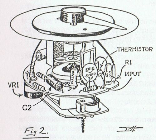
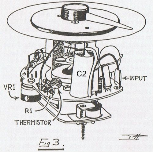
The external white wire loop is the primary of a pulse transformer and the inner circuitry is a simple monostable so a sine wave isn't the best way to trigger it. I started rebuilding these about 25 years ago and always switched the signal generator to sawtooth which more closely replicates the ignition spikes the engine produces. I also fed the signal directly to the input tag on the following drawings from an article I wrote for The Alpine Horn around 20 or so years ago. About 1v p-p via a 0.5μF capacitor with the leading edge of the sawtooth -ve going should work fine.

RVI2404-00500wide.jpg
RVI2411-01500wide.jpg
 

spudman5

Donation Time
Paul,

Thank you for the information on the calibration waveform and using the direct input through the capacitor inside the Tach body.

I have already completed calibration on my Tach and put the glass and chrome ring on, so I probably won't pull it apart anytime soon to re-calibrate with the internal input. However, I will archive your information for when I have to rework my Tach or end up rebuilding any other Tachs.

Thanks,
Mike Tanner
 
Top