• Welcome to the new SAOCA website. Already a member? Simply click Log In/Sign Up up and to the right and use your same username and password from the old site. If you've forgotten your password, please send an email to membership@sunbeamalpine.org for assistance.

    If you're new here, click Log In/Sign Up and enter your information. We'll approve your account as quickly as possible, typically in about 24 hours. If it takes longer, you were probably caught in our spam/scam filter.

    Enjoy.

Mystery (To me) Electrical Part

Shabazz

Donation Time
1962 Series 2 Alpine

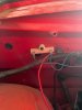
I'm wondering what this item is (see attached pic). It is attached to the firewall of the engine compartment on the passenger side (LHD). It is not actually wired in to anything at the moment. The blue wire you see simply makes a loop. I can't decipher the wiring diagram well enough to find this electrical part. If you know what it is, could you also explain what it does and how it is wired in the vehicle?

Thanks!
 

Attachments

  • IMG_1724.jpg
    IMG_1724.jpg
    39.7 KB · Views: 84

DanR

Diamond Level Sponsor
Usually mounted on the brace arm from the firewall to the fender and mounted near the coil.
 

260Alpine

Silver Level Sponsor
Ballast resistor. Not needed when using some electronic ignitions with low resistance coils.
 
Last edited:

sunalp

Diamond Level Sponsor
That's a ballast resistor. It should mount by your coil, as that reduces the voltage to the coil to keep it
from burning up your points.
Your coil power goes to one side of it then you run another wire to the coil, putting the resistor in line.
 

Shabazz

Donation Time
Thanks all! Thanks Sunalp for such a complete answer! I'm learning on the fly and appreciate the what, where, and why.
 

hartmandm

Moderator
Diamond Level Sponsor
Shabazz,

In a stock setup, the ballast resistor is 1.5 ohms and the ignition coil is 1.5 ohms. A cold weather starting circuit was added to Alpines destined for possible cold weather climates, like North America. The extra wire bypasses the ballast resistor during starting to provide full battery voltage to the coil during start. Then once the car is running, the ballast resistor is back in play to reduce the voltage going to the ignition coil.

What is your ignition setup? A ballast resistor might be of benefit depending upon what setup you have and if you ever find yourself wanting to start your Alpine in colder weather.

There are 3 ohm coils where you would not use the ballast resistor. And if you have an electronic ignition, you might not need it.

Mike
 

Shabazz

Donation Time
Interesting. My dad bought this 62 new, off the lot, in Regina, Saskatchewan. I would imagine it was set up for cold weather. When my dad retired he and his buddies "re-did" (repainted, some interior) the car. When they put it back together, it would appear that not all of the wires were were hooked up again. It might be because they didn't hook the horns back up, some gauges, and perhaps some other stuff, including the ballast resistor.

I'm not sure what you mean by "what is my ignition setup?" as I am learning as I go. I would say the ignition system is what came with the car at purchase, (though the coil looks new) There does not appear to be a bypass, though there is a loose (unattached) solid green wire near the coil. Right now there is a white wire attached to the coil and the blue on the ballast is simply hooked in a loop to each side of the ballast. The car does start and run, so whatever the wires do, they seem to be working (at least well enough). There is also an unattached green wire near the fuse box. When I checked the resistance between the green wire by the coil and the green wire near the fuse box, I get an initial reading on the multimeter, but then it goes down to 0 (zero) very quickly. This is the first time I've measured resistance so I really am just learning and am not sure what to make of that reading...

I live in a cold climate as well, but have no intentions of running the Alpine in the winter, and I do have a heated garage. Though the ballast may not be necessary, I am still interested in accounting for these loose wires!
 

hartmandm

Moderator
Diamond Level Sponsor
Do you have two wires connected to the coil - one white wire and then a white + brown wire that goes from the coil to the distributor?

Do you have a stock Lucas distributor, as opposed to an aftermarket electronic distributor, like a Pertronix? If so, I'd check the ignition coil to determine if it is 1.5 ohms or 3.0 ohms. If the coil is 1.5 ohms, consider adding the ballast resistor back in.

To measure the resistance of the coil (its primary winding), disconnect all of the wires connected to it. Then measure the resistance across the "+" and "-" terminals.

Mike
 

Shabazz

Donation Time
I believe the distributor is stock. I couldn't see markings on the outside, but it has enough grime on it to indicate it has been on the engine for a long time.

The coil: I measured 3.9 ohms the markings on the outside of the coil don't indicate a brand, but it says- 12V Use without external resistor 080. and on the bottom it has ©061512 printed.

Is it possible for it to measure 3.9 ohms? Is it multimeter operator error or cheap multimeter error?
 

BEpine

Platinum Level Sponsor
When using a DVM, (multimeter), connect the 2 leads together and see what that reading is. Then subtract that reading from what your measurement is. My guess is you have a 3 ohm coil and that is why the ballast resistor is not connected.
 

Shabazz

Donation Time
Thanks BEpine. I did that and got a reading of .4--> so 3.5 I'm just going to assume it is 3 ohms, not use the ballast resistor, and move on. I thank you all for your help.
 
Top