• Welcome to the new SAOCA website. Already a member? Simply click Log In/Sign Up up and to the right and use your same username and password from the old site. If you've forgotten your password, please send an email to membership@sunbeamalpine.org for assistance.

    If you're new here, click Log In/Sign Up and enter your information. We'll approve your account as quickly as possible, typically in about 24 hours. If it takes longer, you were probably caught in our spam/scam filter.

    Enjoy.

SI -II Upper steering column identify

DanR

Diamond Level Sponsor
I am trying to figure what these holes are designed by Rootes to accomplish? What fastens into them?Alpine SI -II upper column small holes   20200514_115021.jpg Alpine SI -II upper column more small holes  20200514_115032.jpg

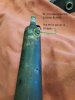
Is the "Plug" or "Knob" in the 1st PIC an alignment for the steering wheel column shroud? If so, which way is the correct position?


In the 3rd PIC ? The "PLUG" ? What is it's purpose?
Alpine Si - ii  upper column with plug 8 inches from steeron hub      20200514_115049.jpg

UP DATE: AS of May 24, 2020: This "plug" was removed by me out of curiosity, and found to be a very hard black plastic about 1/4" in diameter. It protruded into the outer column about a 1/4". So, I'm thinking, before I can in procession of this steering column it (the plug) had been cut off evenly/smoothly.

Another unsolved mystery:)
 
Last edited:

65beam

Donation Time
Dan,
The raised pin holds the directional switch in the proper place on my RHD Harrington.
 

DanR

Diamond Level Sponsor
Dan,
The raised pin holds the directional switch in the proper place on my RHD Harrington.

Thanks for that info! Now, can you tell me the position in which the "pin" sits?

9 o'clock ?; 12 o'clock? or ??
 

DanR

Diamond Level Sponsor
I found an answer to the "position" for the PIN on another steering column I had stuffed away in the shed.

Just can't figure what the 4 small holes are for?

Alpine Si - ii Upper Steering Column  Pin at 11 0 clock position  20200515_174416.jpg
 

Attachments

  • Alpine Si - ii Upper Steering Column  Pin at 11 0 clock position  20200515_174416.jpg
    Alpine Si - ii Upper Steering Column Pin at 11 0 clock position 20200515_174416.jpg
    283.6 KB · Views: 1

Toyanvil

Gold Level Sponsor
I just looked at the two columns I have and they do not have the small holes, yours looks like someone drilled and tapped it to hold the covers. also my series 2 the raised pin is at about 4:30. If you click on the picture it will get larger.
bmw8190IMG_2438-X3.jpg

bmw8190IMG_2438-XL.jpg
 
Last edited:

DanR

Diamond Level Sponsor
John, Thanks for the info....

I have two complete Early series steering columns neither of which have been molested or modified, both have the same set of "four small holes" in the exact same place.
Until I remembered the two complete assemblies, I had no way of determining what position the "pin" sat on the column. Both of them have the "pin" at 11 o'clock

Neither of the steering columns came from the same source.

It appears there is some discrepancy between yours and these two.

The 1st pictures I posted were of a Series I or II upper column and shaft that I had cut the upper 10" off a year or so ago from a damaged steering assy. It matches the two assemblies I pulled from my shed.
 

Alpine Addict

Platinum Donor
Platinum Level Sponsor
Dan my series 2 has the two holes on top and the pin. If memory serves me correctly there is a felt seal underneath, could the holes be something to do with this?
 

Toyanvil

Gold Level Sponsor
That's the funny thing about Sunbeams, my steering box and column have never been removed from my car in the 43 years I have owned it and never looked like it had. With a three bolt pattern at the steering box mine could only be rotated to about 4:00, 8:00 and 12:00. Sorry for the bad pictures, they are all I had from when I redid my dash. If you click on the picture it will get larger.
bmw8180IMG_2428-X3.jpg
 

DanR

Diamond Level Sponsor
Steve, That is part of the mystery! What is the purpose of the 4 small holes?

Toyanvil (John), I have slept on your prior post about the position being about 4:30....Looked at my columns again and believe my pin is at 10:45 -11 o'clock (definitely not 12 o'clock). If the three bolts were removed, the column rotated one (1) hole clockwise the pin would be at maybe 2:45 almost 3 o'clock. One (1) more turn to the next hole it would be at maybe 6:45 - 7 o'clock. Then if turned one (1) more and back to the original position 10:45 - 11 o'clock, both of which are set at what I believe 10:45 or 11 clock positions.

If the purpose of the "pin" is for alignment of the turn signal switch, Is yours or any body else's aligning properly?

This all started because I am attempting to align the "upper" column in a correct position so that I can weld the a three eared "flange" that bolts the upper column to my EPS motor for the electric power steering for an early Series Alpine.
 

Alpine Addict

Platinum Donor
Platinum Level Sponsor
Dan,
As my series 2 is right hand drive I looked at a spare left hand drive steering column I have and the pin appears to be at 11 o Clock.
 

DanR

Diamond Level Sponsor
I came to a conclusion on the "pin" as 11'oclock (give or take a few degrees).

Still no answer for the four (4) small holes on each of my three upper columns.

Thanks for all the input on my questions!
 

DanR

Diamond Level Sponsor
John, I do not have a turn signal switch..... That is what started all of my questions.

While building another EPS, this one for a SII Alpine I ran into a problem as to exactly where the "pin" was located and what was it's purpose.

After lots of time spent trying to get an answer,
I discovered two more of the early Series steering assemblies in my stored "stuff".

They are both set at 11 o'clock.

if you can provide pictures of the "correct mounting of the turn signal switch I'd certainly appreciate it,
 

loose_electron

Donation Time
The two small holes could have been done to meet a manufacturing requirement of alignment in an assembly fixture. A manufacturing jig that holds the tube in a clamping structure that is used to press the bearing in at the end of the tube is a possibility. That way high pressure was not needed to hold the tube from slipping. Just my speculation.
 
Top